

116
H. Rehage and M. Kind
2.2 Experiments
We conducted different types of experiments (Experimental Setups A–D) to provide a
step-by-step validation of our model. Section 2.2.1 presents the experimental setups
for validation of the steady-state model. Section 2.2.2 presents the setup for the
dynamic semi-batch experiments and the “experimental simulation” setup to allow
a specific validation of the equivalent circuit concept for semi-batch precipitation.
2.2.1 Steady State Experiments
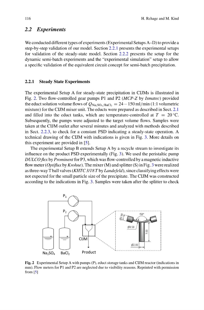
The experimental Setup A for steady-state precipitation in CIJMs is illustrated in
Fig. 2. Two flow-controlled gear pumps P1 and P2 (MCP-Z by Ismatec) provided
the educt solution volume flows of Q Na 2 SO 4 /BaCl 2 = 24−150 ml/min (1:1 volumetric
mixture) for the CIJM mixer unit. The educts were prepared as described in Sect. 2.1
and filled into the educt tanks, which are temperature-controlled at T = 20
◦ C.
Subsequently, the pumps were adjusted to the target volume flows. Samples were
taken at the CIJM outlet after several minutes and analyzed with methods described
in Sect. 2.2.3, to check for a constant PSD indicating a steady-state operation. A
technical drawing of the CIJM with indications is given in Fig. 3. More details on
this experiment are provided in [5].
The experimental Setup B extends Setup A by a recycle stream to investigate its
influence on the product PSD experimentally (Fig. 3). We used the peristaltic pump
DULCO flex by Prominent for P3, which was flow-controlled by a magnetic inductive
flow meter (Optiflux by Krohne). The mixer (M) and splitter (S) in Fig. 3 were realized
as three-way T ball valves (KHTC 3/18 T by Landefeld), since classifying effects were
not expected for the small particle size of the precipitate. The CIJM was constructed
according to the indications in Fig. 3. Samples were taken after the splitter to check
BaCl 2
Na 2 SO 4
P 2
P 1
CIJM
Product
Fig. 2 Experimental Setup A with pumps (P), educt storage tanks and CIJM reactor (indications in
mm). Flow meters for P1 and P2 are neglected due to visibility reasons. Reprinted with permission
from [5]
H. Rehage and M. Kind
2.2 Experiments
We conducted different types of experiments (Experimental Setups A–D) to provide a
step-by-step validation of our model. Section 2.2.1 presents the experimental setups
for validation of the steady-state model. Section 2.2.2 presents the setup for the
dynamic semi-batch experiments and the “experimental simulation” setup to allow
a specific validation of the equivalent circuit concept for semi-batch precipitation.
2.2.1 Steady State Experiments
The experimental Setup A for steady-state precipitation in CIJMs is illustrated in
Fig. 2. Two flow-controlled gear pumps P1 and P2 (MCP-Z by Ismatec) provided
the educt solution volume flows of Q Na 2 SO 4 /BaCl 2 = 24−150 ml/min (1:1 volumetric
mixture) for the CIJM mixer unit. The educts were prepared as described in Sect. 2.1
and filled into the educt tanks, which are temperature-controlled at T = 20
◦ C.
Subsequently, the pumps were adjusted to the target volume flows. Samples were
taken at the CIJM outlet after several minutes and analyzed with methods described
in Sect. 2.2.3, to check for a constant PSD indicating a steady-state operation. A
technical drawing of the CIJM with indications is given in Fig. 3. More details on
this experiment are provided in [5].
The experimental Setup B extends Setup A by a recycle stream to investigate its
influence on the product PSD experimentally (Fig. 3). We used the peristaltic pump
DULCO flex by Prominent for P3, which was flow-controlled by a magnetic inductive
flow meter (Optiflux by Krohne). The mixer (M) and splitter (S) in Fig. 3 were realized
as three-way T ball valves (KHTC 3/18 T by Landefeld), since classifying effects were
not expected for the small particle size of the precipitate. The CIJM was constructed
according to the indications in Fig. 3. Samples were taken after the splitter to check
BaCl 2
Na 2 SO 4
P 2
P 1
CIJM
Product
Fig. 2 Experimental Setup A with pumps (P), educt storage tanks and CIJM reactor (indications in
mm). Flow meters for P1 and P2 are neglected due to visibility reasons. Reprinted with permission
from [5]