

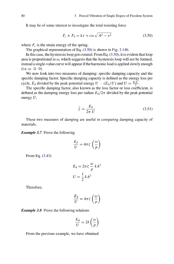
80
3 Forced Vibration of Single Degree of Freedom System
It may be of some interest to investigate the total resisting force
F s + F d = kx + cω
A 2 − x 2
(3.50)
where F s is the strain energy of the spring.
The graphical representation of Eq. (3.50) is shown in Fig. 3.14b.
In this case, the hysteresis loop gets rotated. From Eq. (3.50), it is evident that loop
area is proportional to ω, which suggests that the hysteresis loop will not be formed,
instead a single-value curve will appear if the harmonic load is applied slowly enough
(i.e. ω ∼ = 0).
We now look into two measures of damping: specific damping capacity and the
specific damping factor. Specific damping capacity is defined as the energy loss per
cycle, E d divided by the peak potential energy U · (E d /U ) and U =
K A
2
2
.
The specific damping factor, also known as the loss factor or loss coefficient, is
defined as the damping energy loss per radian E d /2π divided by the peak potential
energy U,
¯
ζ =
E d
2π U
(3.51)
These two measures of damping are useful in comparing damping capacity of
materials.
Example 3.7 Prove the following
E d
U
= 4πζ
ω
p
From Eq. (3.43)
E d = 2πζ
ω
p
k A
2
U =
1
2
k A
2
Therefore,
E d
U
= 4πζ
ω
p
Example 3.8 Prove the following relations
E d
U
= 2δ
ω
p
From the previous example, we have obtained
3 Forced Vibration of Single Degree of Freedom System
It may be of some interest to investigate the total resisting force
F s + F d = kx + cω
A 2 − x 2
(3.50)
where F s is the strain energy of the spring.
The graphical representation of Eq. (3.50) is shown in Fig. 3.14b.
In this case, the hysteresis loop gets rotated. From Eq. (3.50), it is evident that loop
area is proportional to ω, which suggests that the hysteresis loop will not be formed,
instead a single-value curve will appear if the harmonic load is applied slowly enough
(i.e. ω ∼ = 0).
We now look into two measures of damping: specific damping capacity and the
specific damping factor. Specific damping capacity is defined as the energy loss per
cycle, E d divided by the peak potential energy U · (E d /U ) and U =
K A
2
2
.
The specific damping factor, also known as the loss factor or loss coefficient, is
defined as the damping energy loss per radian E d /2π divided by the peak potential
energy U,
¯
ζ =
E d
2π U
(3.51)
These two measures of damping are useful in comparing damping capacity of
materials.
Example 3.7 Prove the following
E d
U
= 4πζ
ω
p
From Eq. (3.43)
E d = 2πζ
ω
p
k A
2
U =
1
2
k A
2
Therefore,
E d
U
= 4πζ
ω
p
Example 3.8 Prove the following relations
E d
U
= 2δ
ω
p
From the previous example, we have obtained