

3.2 Response of Damped Systems to Harmonic Loading
61
Substituting the above values of A and B in Eq. (3.5), we get
x p =
−
F 0
m
· 2nω
( p 2 − ω 2 ) 2 + (2nω) 2 cos ω t +
F 0
m
( p
2
− ω
2
)
( p 2 − ω 2 ) 2 + (2nω) 2 sin ω t
(3.9)
Let
sin ϕ = (2nω) k 1
cos ϕ = ( p
2
− ω
2
) k 1
(3.10)
On substitution of 2nω and ( p
2
− ω
2
) in the numerator of the two terms on the
right hand side, on the basis of Eq. (3.10), we get
x p =
F 0
m
( p 2 − ω 2 ) 2 + (2nω) 2
sin (ω t − ϕ)
(3.11a)
where
ϕ = tan
− 1
2nω
p 2 − ω 2
(3.11b)
The complete solution is given by
x = e
− nt
(C 1 cos
p 2 − n 2 t + C 2 sin
p 2 − n 2 t ) + x p
(3.12)
The first rm on the right hand side having a factor e
− nt represents the free damped
vibration. The other term having the same frequency as the disturbing force represents
forced vibration. The actual motion is a superimposition of two simple harmonic
motions, having different amplitudes, different frequencies and different phases.
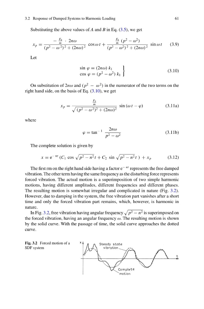
The resulting motion is somewhat irregular and complicated in nature (Fig. 3.2).
However, due to damping in the system, the free vibration part vanishes after a short
time and only the forced vibration part remains, which, however, is harmonic in
nature.
In Fig. 3.2, free vibration having angular frequency
p 2 − n 2 is superimposed on
the forced vibration, having an angular frequency ω. The resulting motion is shown
by the solid curve. With the passage of time, the solid curve approaches the dotted
curve.
Fig. 3.2 Forced motion of a
SDF system
61
Substituting the above values of A and B in Eq. (3.5), we get
x p =
−
F 0
m
· 2nω
( p 2 − ω 2 ) 2 + (2nω) 2 cos ω t +
F 0
m
( p
2
− ω
2
)
( p 2 − ω 2 ) 2 + (2nω) 2 sin ω t
(3.9)
Let
sin ϕ = (2nω) k 1
cos ϕ = ( p
2
− ω
2
) k 1
(3.10)
On substitution of 2nω and ( p
2
− ω
2
) in the numerator of the two terms on the
right hand side, on the basis of Eq. (3.10), we get
x p =
F 0
m
( p 2 − ω 2 ) 2 + (2nω) 2
sin (ω t − ϕ)
(3.11a)
where
ϕ = tan
− 1
2nω
p 2 − ω 2
(3.11b)
The complete solution is given by
x = e
− nt
(C 1 cos
p 2 − n 2 t + C 2 sin
p 2 − n 2 t ) + x p
(3.12)
The first rm on the right hand side having a factor e
− nt represents the free damped
vibration. The other term having the same frequency as the disturbing force represents
forced vibration. The actual motion is a superimposition of two simple harmonic
motions, having different amplitudes, different frequencies and different phases.
The resulting motion is somewhat irregular and complicated in nature (Fig. 3.2).
However, due to damping in the system, the free vibration part vanishes after a short
time and only the forced vibration part remains, which, however, is harmonic in
nature.
In Fig. 3.2, free vibration having angular frequency
p 2 − n 2 is superimposed on
the forced vibration, having an angular frequency ω. The resulting motion is shown
by the solid curve. With the passage of time, the solid curve approaches the dotted
curve.
Fig. 3.2 Forced motion of a
SDF system