

434
11 Vibration of Ship and Aircraft as a Beam
inertia forces acting at stations 1, 2, …, n, then the horizontal translatory equations
of motion for the vibrating ship can be written as
y 1 − y 0 − x 1 θ 0 = a 11 F 1 + a 12 F 2 + · · · + a 1n F n
y 2 − y 0 − x 2 θ 0 = a 21 F 1 + a 22 F 2 + · · · + a 2n F n
. . .
y n − y 0 − x n θ n = a n1 F 1 + a n2 F 2 + · · · + a nn F n
⎫
⎪ ⎪ ⎬
⎪ ⎪ ⎭
(11.22)
If α i is the total angle of twist of station i from the equilibrium position, β i
represents the distance between the centre of mass and the centre of twist at station i
and T 1 , T 2 , T 3 , . . . , T n , are the twisting moments acting at stations 1, 2, . . . , n, then
a set of equations similar to Eq. (11.22) can be written as
α 1 − α 0 = b 11 T 1 + b 12 T 2 + · · · + b 1n T
α 2 − α 0 = b 21 T 1 + b 22 T 2 + · · · + b 2n T
. . .
α n − α 0 = b n1 T 1 + b n2 T 2 + · · · + b nn T
⎫
⎪ ⎪ ⎬
⎪ ⎪ ⎭
(11.23)
The mass is distributed along the centroidal axis. The given mass is replaced by
the same mass distributed along the shear centre axis and a torque of intensity m i s i g
acts at station i, and so is the treatment at all other stations. There is, therefore,
coupled bending and torsion about the shear centre axis.
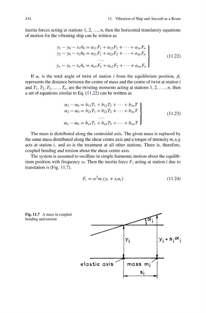
The system is assumed to oscillate in simple harmonic motion about the equilibrium position with frequency ω. Then the inertia force F i acting at station i due to
translation is (Fig. 11.7).
F i = ω
2 m i (y i + s i α i )
(11.24)
Fig. 11.7 A mass in coupled
bending and torsion
11 Vibration of Ship and Aircraft as a Beam
inertia forces acting at stations 1, 2, …, n, then the horizontal translatory equations
of motion for the vibrating ship can be written as
y 1 − y 0 − x 1 θ 0 = a 11 F 1 + a 12 F 2 + · · · + a 1n F n
y 2 − y 0 − x 2 θ 0 = a 21 F 1 + a 22 F 2 + · · · + a 2n F n
. . .
y n − y 0 − x n θ n = a n1 F 1 + a n2 F 2 + · · · + a nn F n
⎫
⎪ ⎪ ⎬
⎪ ⎪ ⎭
(11.22)
If α i is the total angle of twist of station i from the equilibrium position, β i
represents the distance between the centre of mass and the centre of twist at station i
and T 1 , T 2 , T 3 , . . . , T n , are the twisting moments acting at stations 1, 2, . . . , n, then
a set of equations similar to Eq. (11.22) can be written as
α 1 − α 0 = b 11 T 1 + b 12 T 2 + · · · + b 1n T
α 2 − α 0 = b 21 T 1 + b 22 T 2 + · · · + b 2n T
. . .
α n − α 0 = b n1 T 1 + b n2 T 2 + · · · + b nn T
⎫
⎪ ⎪ ⎬
⎪ ⎪ ⎭
(11.23)
The mass is distributed along the centroidal axis. The given mass is replaced by
the same mass distributed along the shear centre axis and a torque of intensity m i s i g
acts at station i, and so is the treatment at all other stations. There is, therefore,
coupled bending and torsion about the shear centre axis.
The system is assumed to oscillate in simple harmonic motion about the equilibrium position with frequency ω. Then the inertia force F i acting at station i due to
translation is (Fig. 11.7).
F i = ω
2 m i (y i + s i α i )
(11.24)
Fig. 11.7 A mass in coupled
bending and torsion