

11.4 The Flexibility Matrix Method for Determining Natural …
433
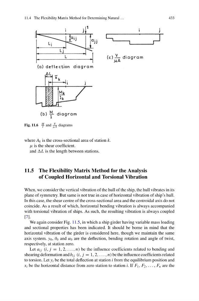
Fig. 11.6
M
I and
V
μA diagrams
where A k is the cross-sectional area of station k.
μ is the shear coefficient.
and L is the length between stations.
11.5 The Flexibility Matrix Method for the Analysis
of Coupled Horizontal and Torsional Vibration
When, we consider the vertical vibration of the hull of the ship, the hull vibrates in its
plane of symmetry. But same is not true in case of horizontal vibration of ship’s hull.
In this case, the shear centre of the cross-sectional area and the centroidal axis do not
coincide. As a result of which, horizontal bending vibration is always accompanied
with torsional vibration of ships. As such, the resulting vibration is always coupled
[7].
We again consider Fig. 11.5, in which a ship girder having variable mass loading
and sectional properties has been indicated. It should be borne in mind that the
horizontal vibration of the girder is considered here, though we maintain the same
axis system. y 0 , θ 0 and α 0 are the deflection, bending rotation and angle of twist,
respectively, at station zero.
Let a i j (i, j = 1, 2, . . . , n) be the influence coefficients related to bending and
shearing deformation and b i j (i, j = 1, 2, . . . , n) be the influence coefficients related
to torsion. Let y i be the total deflection at station i from the equilibrium position and
x i be the horizontal distance from zero station to station i. If F 1 , F 2 , . . . , F n are the
433
Fig. 11.6
M
I and
V
μA diagrams
where A k is the cross-sectional area of station k.
μ is the shear coefficient.
and L is the length between stations.
11.5 The Flexibility Matrix Method for the Analysis
of Coupled Horizontal and Torsional Vibration
When, we consider the vertical vibration of the hull of the ship, the hull vibrates in its
plane of symmetry. But same is not true in case of horizontal vibration of ship’s hull.
In this case, the shear centre of the cross-sectional area and the centroidal axis do not
coincide. As a result of which, horizontal bending vibration is always accompanied
with torsional vibration of ships. As such, the resulting vibration is always coupled
[7].
We again consider Fig. 11.5, in which a ship girder having variable mass loading
and sectional properties has been indicated. It should be borne in mind that the
horizontal vibration of the girder is considered here, though we maintain the same
axis system. y 0 , θ 0 and α 0 are the deflection, bending rotation and angle of twist,
respectively, at station zero.
Let a i j (i, j = 1, 2, . . . , n) be the influence coefficients related to bending and
shearing deformation and b i j (i, j = 1, 2, . . . , n) be the influence coefficients related
to torsion. Let y i be the total deflection at station i from the equilibrium position and
x i be the horizontal distance from zero station to station i. If F 1 , F 2 , . . . , F n are the