

10.7 Dynamic Stiffness Matrix of a Bar Subjected to Axial …
417
= E I
⎡
⎢
⎢
⎣
ε
3
0
ε
3
0
ε
3 cos εL −ε
3 sin εL −ε
3 cos φ L −ε
3 sin φ L
0
−ε
2
0
ε
2
ε
2 sin εL ε
2 cos εL −ε
2 sin φ L ε
2 cos φ L
⎤
⎥
⎥
⎦
⎧
⎪ ⎪ ⎨
⎪ ⎪ ⎩
C 1
C 2
C 3
C 4
⎫
⎪ ⎪ ⎬
⎪ ⎪ ⎭
(10.76)
or
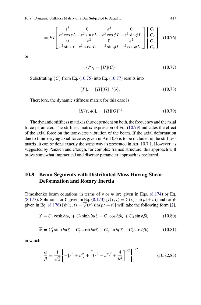
{P} e = [H ]{C}
(10.77)
Substituting {C} from Eq. (10.75) into Eq. (10.77) results into
{P} e = [H ][G]
−1
{δ} e
(10.78)
Therefore, the dynamic stiffness matrix for this case is
[K (ε, φ)] e = [H ][G]
−1
(10.79)
The dynamic stiffness matrix is thus dependent on both, the frequency and the axial
force parameter. The stiffness matrix expression of Eq. (10.79) indicates the effect
of the axial force on the transverse vibration of the beam. If the axial deformation
due to time-varying axial force as given in Art 10.6 is to be included in the stiffness
matrix, it can be done exactly the same way as presented in Art. 10.7.1. However, as
suggested by Penzien and Clough, for complex framed structure, this approach will
prove somewhat impractical and discrete parameter approach is preferred.
10.8 Beam Segments with Distributed Mass Having Shear
Deformation and Rotary Inertia
Timoshenko beam equations in terms of y or ψ are given in Eqs. (8.174) or Eq.
(8.177). Solutions for Y given in Eq. (8.173) [y(x, t) = Y (x) sin( pt + ε)] and for ψ
given in Eq. (8.176) [ψ(x, t) = ψ(x) sin( pt + ε)] will take the following form [2].
Y = C 1 cosh bαξ + C 2 sinh bαξ + C 3 cos bβξ + C 4 sin bβξ
(10.80)
ψ = C
1 sinh bαξ + C
2 cosh bαξ + C
3 sin bβξ + C
4 cos bβξ
(10.81)
in which
α
β
=
1
√
2
−
r
2
+ s
2
+
r
2
− s
2
2 +
4
b 2
1/2
1/2
(10.82,83)
417
= E I
⎡
⎢
⎢
⎣
ε
3
0
ε
3
0
ε
3 cos εL −ε
3 sin εL −ε
3 cos φ L −ε
3 sin φ L
0
−ε
2
0
ε
2
ε
2 sin εL ε
2 cos εL −ε
2 sin φ L ε
2 cos φ L
⎤
⎥
⎥
⎦
⎧
⎪ ⎪ ⎨
⎪ ⎪ ⎩
C 1
C 2
C 3
C 4
⎫
⎪ ⎪ ⎬
⎪ ⎪ ⎭
(10.76)
or
{P} e = [H ]{C}
(10.77)
Substituting {C} from Eq. (10.75) into Eq. (10.77) results into
{P} e = [H ][G]
−1
{δ} e
(10.78)
Therefore, the dynamic stiffness matrix for this case is
[K (ε, φ)] e = [H ][G]
−1
(10.79)
The dynamic stiffness matrix is thus dependent on both, the frequency and the axial
force parameter. The stiffness matrix expression of Eq. (10.79) indicates the effect
of the axial force on the transverse vibration of the beam. If the axial deformation
due to time-varying axial force as given in Art 10.6 is to be included in the stiffness
matrix, it can be done exactly the same way as presented in Art. 10.7.1. However, as
suggested by Penzien and Clough, for complex framed structure, this approach will
prove somewhat impractical and discrete parameter approach is preferred.
10.8 Beam Segments with Distributed Mass Having Shear
Deformation and Rotary Inertia
Timoshenko beam equations in terms of y or ψ are given in Eqs. (8.174) or Eq.
(8.177). Solutions for Y given in Eq. (8.173) [y(x, t) = Y (x) sin( pt + ε)] and for ψ
given in Eq. (8.176) [ψ(x, t) = ψ(x) sin( pt + ε)] will take the following form [2].
Y = C 1 cosh bαξ + C 2 sinh bαξ + C 3 cos bβξ + C 4 sin bβξ
(10.80)
ψ = C
1 sinh bαξ + C
2 cosh bαξ + C
3 sin bβξ + C
4 cos bβξ
(10.81)
in which
α
β
=
1
√
2
−
r
2
+ s
2
+
r
2
− s
2
2 +
4
b 2
1/2
1/2
(10.82,83)