

7.5 Damping in MDF Systems
279
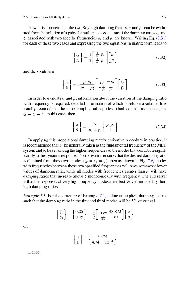
Now, it is apparent that the two Rayleigh damping factors, α and β, can be evaluated from the solution of a pair of simultaneous equations if the damping ratios ζ r and
ζ s associated with two specific frequencies p r and p s are known. Writing Eq. (7.31)
for each of these two cases and expressing the two equations in matrix form leads to
ζ r
ζ s
=
1
2
1
p r
p r
1
p s
p s
α
β
(7.32)
and the solution is
α
β
= 2
p r p s
p 2
r − p 2
s
p r − p s
−
1
p r
1
p s
ζ r
ζ s
(7.33)
In order to evaluate α and β, information about the variation of the damping ratio
with frequency is required, detailed information of which is seldom available. It is
usually assumed that the same damping ratio applies to both control frequencies, i.e.
ζ r = ζ s = ζ . In this case, then
α
β
=
2ζ
p r + p s
p r p s
1
(7.34)
In applying this proportional damping matrix derivative procedure in practice, it
is recommended that p r be generally taken as the fundamental frequency of the MDF
system and p s be set among the higher frequencies of the modes that contribute significantly to the dynamic response. The derivation ensures that the desired damping ratio
is obtained from these two modes (ζ r = ζ s = ζ ), then as shown in Fig. 7.6, modes
with frequencies between these two specified frequencies will have somewhat lower
values of damping ratio, while all modes with frequencies greater than p s will have
damping ratios that increase above ζ monotonically with frequency. The end result
is that the responses of very high frequency modes are effectively eliminated by their
high damping ratios.
Example 7.5 For the structure of Example 7.1, define an explicit damping matrix
such that the damping ratio in the first and third modes will be 5% of critical.
ζ 1
ζ 3
=
0.05
0.05
=
1
2
1
43.872
43.872
1
167
167
α
β
or,
α
β
=
3.474
4.74 × 10
−4
Hence,
279
Now, it is apparent that the two Rayleigh damping factors, α and β, can be evaluated from the solution of a pair of simultaneous equations if the damping ratios ζ r and
ζ s associated with two specific frequencies p r and p s are known. Writing Eq. (7.31)
for each of these two cases and expressing the two equations in matrix form leads to
ζ r
ζ s
=
1
2
1
p r
p r
1
p s
p s
α
β
(7.32)
and the solution is
α
β
= 2
p r p s
p 2
r − p 2
s
p r − p s
−
1
p r
1
p s
ζ r
ζ s
(7.33)
In order to evaluate α and β, information about the variation of the damping ratio
with frequency is required, detailed information of which is seldom available. It is
usually assumed that the same damping ratio applies to both control frequencies, i.e.
ζ r = ζ s = ζ . In this case, then
α
β
=
2ζ
p r + p s
p r p s
1
(7.34)
In applying this proportional damping matrix derivative procedure in practice, it
is recommended that p r be generally taken as the fundamental frequency of the MDF
system and p s be set among the higher frequencies of the modes that contribute significantly to the dynamic response. The derivation ensures that the desired damping ratio
is obtained from these two modes (ζ r = ζ s = ζ ), then as shown in Fig. 7.6, modes
with frequencies between these two specified frequencies will have somewhat lower
values of damping ratio, while all modes with frequencies greater than p s will have
damping ratios that increase above ζ monotonically with frequency. The end result
is that the responses of very high frequency modes are effectively eliminated by their
high damping ratios.
Example 7.5 For the structure of Example 7.1, define an explicit damping matrix
such that the damping ratio in the first and third modes will be 5% of critical.
ζ 1
ζ 3
=
0.05
0.05
=
1
2
1
43.872
43.872
1
167
167
α
β
or,
α
β
=
3.474
4.74 × 10
−4
Hence,