

396
S. Papaefthymiou
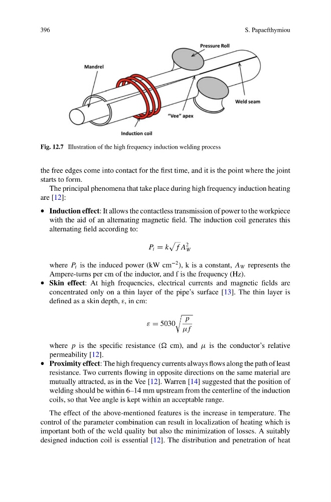
Fig. 12.7 Illustration of the high frequency induction welding process
the free edges come into contact for the first time, and it is the point where the joint
starts to form.
The principal phenomena that take place during high frequency induction heating
are [12]:
• Induction effect: It allows the contactless transmission of power to the workpiece
with the aid of an alternating magnetic field. The induction coil generates this
alternating field according to:
P i = k
f A
2
W
where P i is the induced power (kW cm
−2 ), k is a constant, A W represents the
Ampere-turns per cm of the inductor, and f is the frequency (Hz).
• Skin effect: At high frequencies, electrical currents and magnetic fields are
concentrated only on a thin layer of the pipe’s surface [13]. The thin layer is
defined as a skin depth, ε, in cm:
ε = 5030
p
μf
where p is the specific resistance ( cm), and μ is the conductor’s relative
permeability [12].
• Proximity effect: The high frequency currents always flows along the path of least
resistance. Two currents flowing in opposite directions on the same material are
mutually attracted, as in the Vee [12]. Warren [14] suggested that the position of
welding should be within 6–14 mm upstream from the centerline of the induction
coils, so that Vee angle is kept within an acceptable range.
The effect of the above-mentioned features is the increase in temperature. The
control of the parameter combination can result in localization of heating which is
important both of the weld quality but also the minimization of losses. A suitably
designed induction coil is essential [12]. The distribution and penetration of heat
S. Papaefthymiou
Fig. 12.7 Illustration of the high frequency induction welding process
the free edges come into contact for the first time, and it is the point where the joint
starts to form.
The principal phenomena that take place during high frequency induction heating
are [12]:
• Induction effect: It allows the contactless transmission of power to the workpiece
with the aid of an alternating magnetic field. The induction coil generates this
alternating field according to:
P i = k
f A
2
W
where P i is the induced power (kW cm
−2 ), k is a constant, A W represents the
Ampere-turns per cm of the inductor, and f is the frequency (Hz).
• Skin effect: At high frequencies, electrical currents and magnetic fields are
concentrated only on a thin layer of the pipe’s surface [13]. The thin layer is
defined as a skin depth, ε, in cm:
ε = 5030
p
μf
where p is the specific resistance ( cm), and μ is the conductor’s relative
permeability [12].
• Proximity effect: The high frequency currents always flows along the path of least
resistance. Two currents flowing in opposite directions on the same material are
mutually attracted, as in the Vee [12]. Warren [14] suggested that the position of
welding should be within 6–14 mm upstream from the centerline of the induction
coils, so that Vee angle is kept within an acceptable range.
The effect of the above-mentioned features is the increase in temperature. The
control of the parameter combination can result in localization of heating which is
important both of the weld quality but also the minimization of losses. A suitably
designed induction coil is essential [12]. The distribution and penetration of heat