

330
Y. Shi et al.
M r
−1
=
Q m
Q
=
r m + 2r m
2
)
2(2r m + 1)
2
exp
−r m
r m + 1
(10.14)
where r m is the maximum of the value of
v R
2α
.
10.2.6.4 Recent Research on Heat Input of K-TIG Welding
Fei’s study showed that the heat input was another factor except for travel speed that
influenced the undercut defect forming, because it changed the plasma jet trajectory
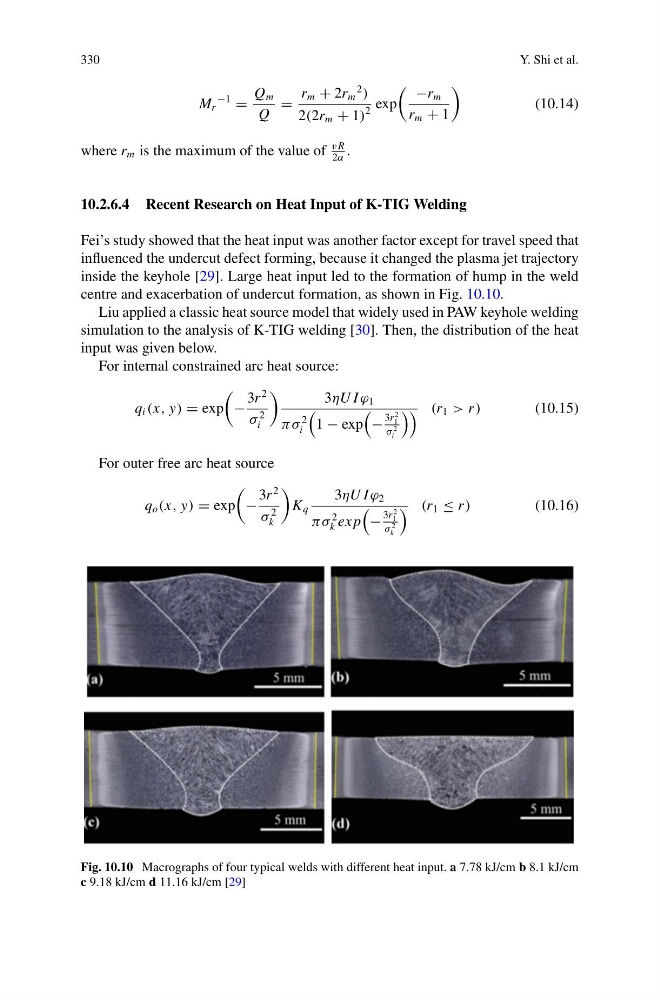
inside the keyhole [29]. Large heat input led to the formation of hump in the weld
centre and exacerbation of undercut formation, as shown in Fig. 10.10.
Liu applied a classic heat source model that widely used in PAW keyhole welding
simulation to the analysis of K-TIG welding [30]. Then, the distribution of the heat
input was given below.
For internal constrained arc heat source:
q i (x, y) = exp
−
3r
2
σ
2
i
3ηU I ϕ 1
πσ
2
i
1 − exp
−
3r
2
1
σ
2
i
(r 1 > r )
(10.15)
For outer free arc heat source
q o (x, y) = exp
−
3r
2
σ
2
k
K q
3ηU I ϕ 2
πσ
2
k ex p
−
3r
2
1
σ
2
k
(r 1 ≤ r )
(10.16)
Fig. 10.10 Macrographs of four typical welds with different heat input. a 7.78 kJ/cm b 8.1 kJ/cm
c 9.18 kJ/cm d 11.16 kJ/cm [29]
Y. Shi et al.
M r
−1
=
Q m
Q
=
r m + 2r m
2
)
2(2r m + 1)
2
exp
−r m
r m + 1
(10.14)
where r m is the maximum of the value of
v R
2α
.
10.2.6.4 Recent Research on Heat Input of K-TIG Welding
Fei’s study showed that the heat input was another factor except for travel speed that
influenced the undercut defect forming, because it changed the plasma jet trajectory
inside the keyhole [29]. Large heat input led to the formation of hump in the weld
centre and exacerbation of undercut formation, as shown in Fig. 10.10.
Liu applied a classic heat source model that widely used in PAW keyhole welding
simulation to the analysis of K-TIG welding [30]. Then, the distribution of the heat
input was given below.
For internal constrained arc heat source:
q i (x, y) = exp
−
3r
2
σ
2
i
3ηU I ϕ 1
πσ
2
i
1 − exp
−
3r
2
1
σ
2
i
(r 1 > r )
(10.15)
For outer free arc heat source
q o (x, y) = exp
−
3r
2
σ
2
k
K q
3ηU I ϕ 2
πσ
2
k ex p
−
3r
2
1
σ
2
k
(r 1 ≤ r )
(10.16)
Fig. 10.10 Macrographs of four typical welds with different heat input. a 7.78 kJ/cm b 8.1 kJ/cm
c 9.18 kJ/cm d 11.16 kJ/cm [29]