

10 A Novel High-Efficiency Keyhole Tungsten Inert Gas …
329
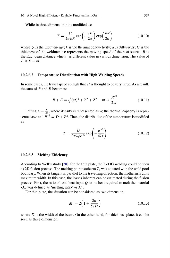
While in three dimension, it is modified as:
T =
Q
2π k R
exp
−
v E
2α
exp
v R
2α
(10.10)
where Q is the input energy; k is the thermal conductivity; α is diffusivity; G is the
thickness of the weldment; v represents the moving speed of the heat source. R is
the Euclidean distance which has different value in various dimension. The value of
E is X − vt.
10.2.6.2 Temperature Distribution with High Welding Speeds
In some cases, the travel speed so high that vt is thought to be very large. As a result,
the sum of R and E becomes:
R + E =
(vt)
2
+ Y 2 + Z 2 − vt ≈
R
∗2
2vt
(10.11)
Letting λ =
k
ρc
, where density is represented as ρ; the thermal capacity is represented as c and R
∗2
= Y
2
+ Z
2 . Then, the distribution of the temperature is modified
as
T =
Q
2πλρcR
exp
−
R
∗2
4λt
(10.12)
10.2.6.3 Melting Efficiency
According to Well’s study [28], for the thin plate, the K-TIG welding could be seen
as 2D fusion process. The melting point isotherm T c was equated with the weld pool
boundary. When its tangent is parallel to the travelling direction, the isotherm is at its
maximum width. In this case, the losses inherent can be estimated during the fusion
process. First, the ratio of total heat input Q to the heat required to melt the material
Q m was defined as ‘melting ratio’ or M r .
For thin plate, the situation can be considered as two dimension:
M r = 2
1 +
2α
5v D
(10.13)
where D is the width of the beam. On the other hand, for thickness plate, it can be
seen as three dimension:
329
While in three dimension, it is modified as:
T =
Q
2π k R
exp
−
v E
2α
exp
v R
2α
(10.10)
where Q is the input energy; k is the thermal conductivity; α is diffusivity; G is the
thickness of the weldment; v represents the moving speed of the heat source. R is
the Euclidean distance which has different value in various dimension. The value of
E is X − vt.
10.2.6.2 Temperature Distribution with High Welding Speeds
In some cases, the travel speed so high that vt is thought to be very large. As a result,
the sum of R and E becomes:
R + E =
(vt)
2
+ Y 2 + Z 2 − vt ≈
R
∗2
2vt
(10.11)
Letting λ =
k
ρc
, where density is represented as ρ; the thermal capacity is represented as c and R
∗2
= Y
2
+ Z
2 . Then, the distribution of the temperature is modified
as
T =
Q
2πλρcR
exp
−
R
∗2
4λt
(10.12)
10.2.6.3 Melting Efficiency
According to Well’s study [28], for the thin plate, the K-TIG welding could be seen
as 2D fusion process. The melting point isotherm T c was equated with the weld pool
boundary. When its tangent is parallel to the travelling direction, the isotherm is at its
maximum width. In this case, the losses inherent can be estimated during the fusion
process. First, the ratio of total heat input Q to the heat required to melt the material
Q m was defined as ‘melting ratio’ or M r .
For thin plate, the situation can be considered as two dimension:
M r = 2
1 +
2α
5v D
(10.13)
where D is the width of the beam. On the other hand, for thickness plate, it can be
seen as three dimension: