

9 Comparative Study of Laser Weldability of Titanium Alloys
305
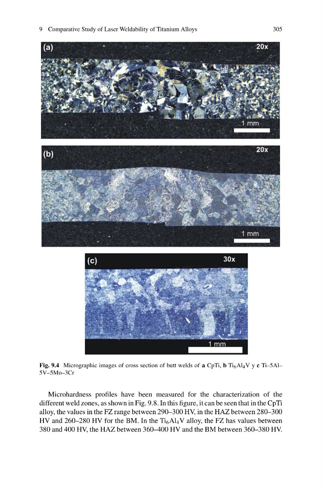
Fig. 9.4 Micrographic images of cross section of butt welds of a CpTi, b Ti 6 Al 4 V y c Ti–5Al–
5V–5Mo–3Cr
Microhardness profiles have been measured for the characterization of the
different weld zones, as shown in Fig. 9.8. In this figure, it can be seen that in the CpTi
alloy, the values in the FZ range between 290–300 HV, in the HAZ between 280–300
HV and 260–280 HV for the BM. In the Ti 6 Al 4 V alloy, the FZ has values between
380 and 400 HV, the HAZ between 360–400 HV and the BM between 360–380 HV.
305
Fig. 9.4 Micrographic images of cross section of butt welds of a CpTi, b Ti 6 Al 4 V y c Ti–5Al–
5V–5Mo–3Cr
Microhardness profiles have been measured for the characterization of the
different weld zones, as shown in Fig. 9.8. In this figure, it can be seen that in the CpTi
alloy, the values in the FZ range between 290–300 HV, in the HAZ between 280–300
HV and 260–280 HV for the BM. In the Ti 6 Al 4 V alloy, the FZ has values between
380 and 400 HV, the HAZ between 360–400 HV and the BM between 360–380 HV.