

188
S. Sahu et al.
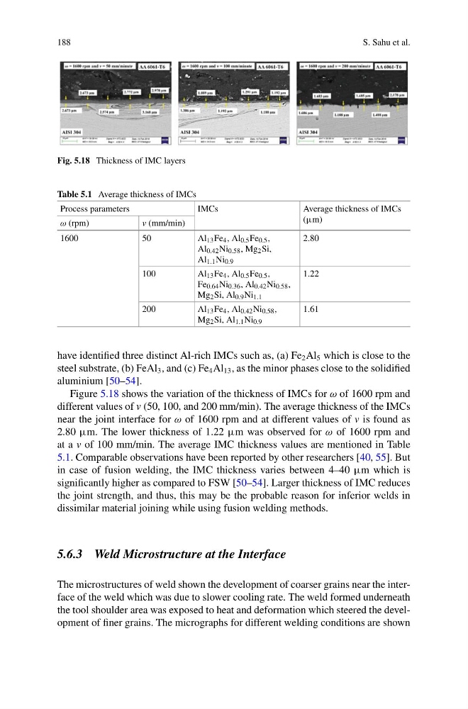
Fig. 5.18 Thickness of IMC layers
Table 5.1 Average thickness of IMCs
Process parameters
IMCs
Average thickness of IMCs
(μm)
ω (rpm)
v (mm/min)
1600
50
Al 13 Fe 4 , Al 0.5 Fe 0.5 ,
Al 0.42 Ni 0.58 , Mg 2 Si,
Al 1.1 Ni 0.9
2.80
100
Al 13 Fe 4 , Al 0.5 Fe 0.5 ,
Fe 0.64 Ni 0.36 , Al 0.42 Ni 0.58 ,
Mg 2 Si, Al 0.9 Ni 1.1
1.22
200
Al 13 Fe 4 , Al 0.42 Ni 0.58 ,
Mg 2 Si, Al 1.1 Ni 0.9
1.61
have identified three distinct Al-rich IMCs such as, (a) Fe 2 Al 5 which is close to the
steel substrate, (b) FeAl 3 , and (c) Fe 4 Al 13 , as the minor phases close to the solidified
aluminium [50–54].
Figure 5.18 shows the variation of the thickness of IMCs for ω of 1600 rpm and
different values of v (50, 100, and 200 mm/min). The average thickness of the IMCs
near the joint interface for ω of 1600 rpm and at different values of v is found as
2.80 μm. The lower thickness of 1.22 μm was observed for ω of 1600 rpm and
at a v of 100 mm/min. The average IMC thickness values are mentioned in Table
5.1. Comparable observations have been reported by other researchers [40, 55]. But
in case of fusion welding, the IMC thickness varies between 4–40 μm which is
significantly higher as compared to FSW [50–54]. Larger thickness of IMC reduces
the joint strength, and thus, this may be the probable reason for inferior welds in
dissimilar material joining while using fusion welding methods.
5.6.3 Weld Microstructure at the Interface
The microstructures of weld shown the development of coarser grains near the interface of the weld which was due to slower cooling rate. The weld formed underneath
the tool shoulder area was exposed to heat and deformation which steered the development of finer grains. The micrographs for different welding conditions are shown
S. Sahu et al.
Fig. 5.18 Thickness of IMC layers
Table 5.1 Average thickness of IMCs
Process parameters
IMCs
Average thickness of IMCs
(μm)
ω (rpm)
v (mm/min)
1600
50
Al 13 Fe 4 , Al 0.5 Fe 0.5 ,
Al 0.42 Ni 0.58 , Mg 2 Si,
Al 1.1 Ni 0.9
2.80
100
Al 13 Fe 4 , Al 0.5 Fe 0.5 ,
Fe 0.64 Ni 0.36 , Al 0.42 Ni 0.58 ,
Mg 2 Si, Al 0.9 Ni 1.1
1.22
200
Al 13 Fe 4 , Al 0.42 Ni 0.58 ,
Mg 2 Si, Al 1.1 Ni 0.9
1.61
have identified three distinct Al-rich IMCs such as, (a) Fe 2 Al 5 which is close to the
steel substrate, (b) FeAl 3 , and (c) Fe 4 Al 13 , as the minor phases close to the solidified
aluminium [50–54].
Figure 5.18 shows the variation of the thickness of IMCs for ω of 1600 rpm and
different values of v (50, 100, and 200 mm/min). The average thickness of the IMCs
near the joint interface for ω of 1600 rpm and at different values of v is found as
2.80 μm. The lower thickness of 1.22 μm was observed for ω of 1600 rpm and
at a v of 100 mm/min. The average IMC thickness values are mentioned in Table
5.1. Comparable observations have been reported by other researchers [40, 55]. But
in case of fusion welding, the IMC thickness varies between 4–40 μm which is
significantly higher as compared to FSW [50–54]. Larger thickness of IMC reduces
the joint strength, and thus, this may be the probable reason for inferior welds in
dissimilar material joining while using fusion welding methods.
5.6.3 Weld Microstructure at the Interface
The microstructures of weld shown the development of coarser grains near the interface of the weld which was due to slower cooling rate. The weld formed underneath
the tool shoulder area was exposed to heat and deformation which steered the development of finer grains. The micrographs for different welding conditions are shown