

3 Modeling of Friction Stir Welding Processes
105
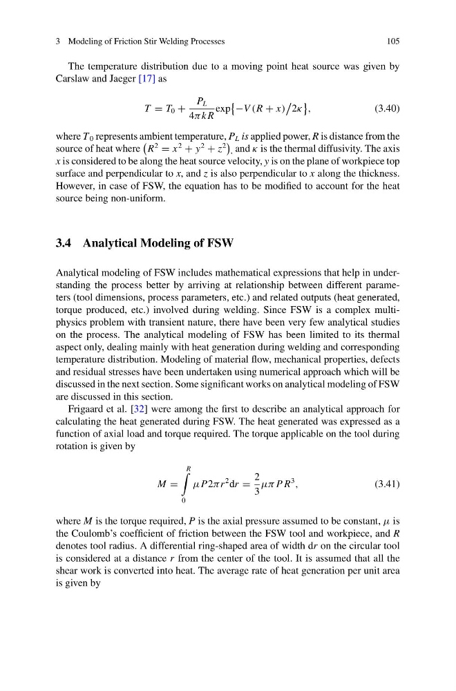
The temperature distribution due to a moving point heat source was given by
Carslaw and Jaeger [17] as
T = T 0 +
P L
4π k R
exp
−V (R + x)
2κ
,
(3.40)
where T 0 represents ambient temperature, P L is applied power, R is distance from the
source of heat where
R
2
= x
2
+ y
2
+ z
2
, and κ is the thermal diffusivity. The axis
x is considered to be along the heat source velocity, y is on the plane of workpiece top
surface and perpendicular to x, and z is also perpendicular to x along the thickness.
However, in case of FSW, the equation has to be modified to account for the heat
source being non-uniform.
3.4 Analytical Modeling of FSW
Analytical modeling of FSW includes mathematical expressions that help in understanding the process better by arriving at relationship between different parameters (tool dimensions, process parameters, etc.) and related outputs (heat generated,
torque produced, etc.) involved during welding. Since FSW is a complex multiphysics problem with transient nature, there have been very few analytical studies
on the process. The analytical modeling of FSW has been limited to its thermal
aspect only, dealing mainly with heat generation during welding and corresponding
temperature distribution. Modeling of material flow, mechanical properties, defects
and residual stresses have been undertaken using numerical approach which will be
discussed in the next section. Some significant works on analytical modeling of FSW
are discussed in this section.
Frigaard et al. [32] were among the first to describe an analytical approach for
calculating the heat generated during FSW. The heat generated was expressed as a
function of axial load and torque required. The torque applicable on the tool during
rotation is given by
M =
R
0
μP2πr
2 dr =
2
3
μπ P R
3
,
(3.41)
where M is the torque required, P is the axial pressure assumed to be constant, μ is
the Coulomb’s coefficient of friction between the FSW tool and workpiece, and R
denotes tool radius. A differential ring-shaped area of width dr on the circular tool
is considered at a distance r from the center of the tool. It is assumed that all the
shear work is converted into heat. The average rate of heat generation per unit area
is given by
105
The temperature distribution due to a moving point heat source was given by
Carslaw and Jaeger [17] as
T = T 0 +
P L
4π k R
exp
−V (R + x)
2κ
,
(3.40)
where T 0 represents ambient temperature, P L is applied power, R is distance from the
source of heat where
R
2
= x
2
+ y
2
+ z
2
, and κ is the thermal diffusivity. The axis
x is considered to be along the heat source velocity, y is on the plane of workpiece top
surface and perpendicular to x, and z is also perpendicular to x along the thickness.
However, in case of FSW, the equation has to be modified to account for the heat
source being non-uniform.
3.4 Analytical Modeling of FSW
Analytical modeling of FSW includes mathematical expressions that help in understanding the process better by arriving at relationship between different parameters (tool dimensions, process parameters, etc.) and related outputs (heat generated,
torque produced, etc.) involved during welding. Since FSW is a complex multiphysics problem with transient nature, there have been very few analytical studies
on the process. The analytical modeling of FSW has been limited to its thermal
aspect only, dealing mainly with heat generation during welding and corresponding
temperature distribution. Modeling of material flow, mechanical properties, defects
and residual stresses have been undertaken using numerical approach which will be
discussed in the next section. Some significant works on analytical modeling of FSW
are discussed in this section.
Frigaard et al. [32] were among the first to describe an analytical approach for
calculating the heat generated during FSW. The heat generated was expressed as a
function of axial load and torque required. The torque applicable on the tool during
rotation is given by
M =
R
0
μP2πr
2 dr =
2
3
μπ P R
3
,
(3.41)
where M is the torque required, P is the axial pressure assumed to be constant, μ is
the Coulomb’s coefficient of friction between the FSW tool and workpiece, and R
denotes tool radius. A differential ring-shaped area of width dr on the circular tool
is considered at a distance r from the center of the tool. It is assumed that all the
shear work is converted into heat. The average rate of heat generation per unit area
is given by