

106
N. Bhardwaj et al.
q 0 =
R
0
ωμP2πr
2 dr ,
(3.42)
where ω is the angular velocity in rad/s. If the tool rotates at N revolutions per second
(rps), then ω = 2π N and
q 0 =
R
0
4π
2
μP Nr
2 dr =
4
3
π
2
μP N R
3
,
(3.43)
Frigaard et al. [32] considered the tool to be a flat shoulder pinless tool, thus
ignored the contribution from the pin in heat generation. Schmidt et al. [72] considered the contributions in heat generation from different parts of tool separately. The
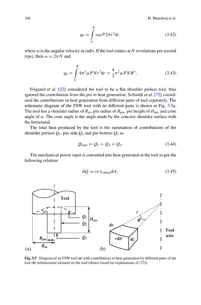
schematic diagram of the FSW tool with its different parts is shown in Fig. 3.5a.
The tool has a shoulder radius of R sh , pin radius of R pin , pin height of H pin and cone
angle of α. The cone angle is the angle made by the concave shoulder surface with
the horizontal.
The total heat produced by the tool is the summation of contributions of the
shoulder portion Q 1 , pin side Q 2 and pin bottom Q 3 as
Q total = Q 1 + Q 2 + Q 3 .
(3.44)
The mechanical power input is converted into heat generated at the tool as per the
following relation:
dQ = ωr τ contact dA,
(3.45)
Fig. 3.5 Diagram of an FSW tool (a) with contributions to heat generation by different parts of the
tool (b) infinitesimal element on the tool (drawn based on explanations of [72])
N. Bhardwaj et al.
q 0 =
R
0
ωμP2πr
2 dr ,
(3.42)
where ω is the angular velocity in rad/s. If the tool rotates at N revolutions per second
(rps), then ω = 2π N and
q 0 =
R
0
4π
2
μP Nr
2 dr =
4
3
π
2
μP N R
3
,
(3.43)
Frigaard et al. [32] considered the tool to be a flat shoulder pinless tool, thus
ignored the contribution from the pin in heat generation. Schmidt et al. [72] considered the contributions in heat generation from different parts of tool separately. The
schematic diagram of the FSW tool with its different parts is shown in Fig. 3.5a.
The tool has a shoulder radius of R sh , pin radius of R pin , pin height of H pin and cone
angle of α. The cone angle is the angle made by the concave shoulder surface with
the horizontal.
The total heat produced by the tool is the summation of contributions of the
shoulder portion Q 1 , pin side Q 2 and pin bottom Q 3 as
Q total = Q 1 + Q 2 + Q 3 .
(3.44)
The mechanical power input is converted into heat generated at the tool as per the
following relation:
dQ = ωr τ contact dA,
(3.45)
Fig. 3.5 Diagram of an FSW tool (a) with contributions to heat generation by different parts of the
tool (b) infinitesimal element on the tool (drawn based on explanations of [72])