

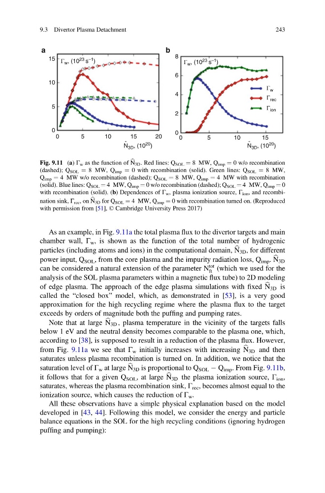
As an example, in Fig. 9.11a the total plasma flux to the divertor targets and main
chamber wall, Γ w , is shown as the function of the total number of hydrogenic
particles (including atoms and ions) in the computational domain, b
N 3D , for different
power input, Q SOL , from the core plasma and the impurity radiation loss, Q imp . b
N 3D
can be considered a natural extension of the parameter N
tot
ft (which we used for the
analysis of the SOL plasma parameters within a magnetic flux tube) to 2D modeling
of edge plasma. The approach of the edge plasma simulations with fixed b
N 3D is
called the “closed box” model, which, as demonstrated in [53], is a very good
approximation for the high recycling regime where the plasma flux to the target
exceeds by orders of magnitude both the puffing and pumping rates.
Note that at large b
N 3D , plasma temperature in the vicinity of the targets falls
below 1 eV and the neutral density becomes comparable to the plasma one, which,
according to [38], is supposed to result in a reduction of the plasma flux. However,
from Fig. 9.11a we see that Γ w initially increases with increasing b
N 3D and then
saturates unless plasma recombination is turned on. In addition, we notice that the
saturation level of Γ w at large b
N 3D is proportional to Q SOL À Q imp . From Fig. 9.11b,
it follows that for a given Q SOL , at large b
N 3D the plasma ionization source, Γ ion ,
saturates, whereas the plasma recombination sink, Γ rec , becomes almost equal to the
ionization source, which causes the reduction of Γ w .
All these observations have a simple physical explanation based on the model
developed in [43, 44]. Following this model, we consider the energy and particle
balance equations in the SOL for the high recycling conditions (ignoring hydrogen
puffing and pumping):
15
a
b
8
6
4
2
0
10
5
0
0
5
10
20
15
0
5
10
15
N 3D , (10
20 )
ˆ
Γ w , (10
23 s
–1 )
Γ w , (10 23 s –1 )
Γ w
Γ rec
Γ ion
N 3D , (10
20 )
ˆ
Fig. 9.11 (a) Γ w as the function of b
N 3D . Red lines: Q SOL ¼ 8 MW, Q imp ¼ 0 w/o recombination
(dashed); Q SOL ¼ 8 MW, Q imp ¼ 0 with recombination (solid). Green lines: Q SOL ¼ 8 MW,
Q imp ¼ 4 MW w/o recombination (dashed); Q SOL ¼ 8 MW, Q imp ¼ 4 MW with recombination
(solid). Blue lines: Q SOL ¼ 4 MW, Q imp ¼ 0 w/o recombination (dashed); Q SOL ¼ 4 MW, Q imp ¼ 0
with recombination (solid). (b) Dependences of Γ w , plasma ionization source, Γ ion , and recombination sink, Γ rec , on b
N 3D for Q SOL ¼ 4 MW, Q imp ¼ 0 with recombination turned on. (Reproduced
with permission from [51], © Cambridge University Press 2017)
9.3 Divertor Plasma Detachment
243
chamber wall, Γ w , is shown as the function of the total number of hydrogenic
particles (including atoms and ions) in the computational domain, b
N 3D , for different
power input, Q SOL , from the core plasma and the impurity radiation loss, Q imp . b
N 3D
can be considered a natural extension of the parameter N
tot
ft (which we used for the
analysis of the SOL plasma parameters within a magnetic flux tube) to 2D modeling
of edge plasma. The approach of the edge plasma simulations with fixed b
N 3D is
called the “closed box” model, which, as demonstrated in [53], is a very good
approximation for the high recycling regime where the plasma flux to the target
exceeds by orders of magnitude both the puffing and pumping rates.
Note that at large b
N 3D , plasma temperature in the vicinity of the targets falls
below 1 eV and the neutral density becomes comparable to the plasma one, which,
according to [38], is supposed to result in a reduction of the plasma flux. However,
from Fig. 9.11a we see that Γ w initially increases with increasing b
N 3D and then
saturates unless plasma recombination is turned on. In addition, we notice that the
saturation level of Γ w at large b
N 3D is proportional to Q SOL À Q imp . From Fig. 9.11b,
it follows that for a given Q SOL , at large b
N 3D the plasma ionization source, Γ ion ,
saturates, whereas the plasma recombination sink, Γ rec , becomes almost equal to the
ionization source, which causes the reduction of Γ w .
All these observations have a simple physical explanation based on the model
developed in [43, 44]. Following this model, we consider the energy and particle
balance equations in the SOL for the high recycling conditions (ignoring hydrogen
puffing and pumping):
15
a
b
8
6
4
2
0
10
5
0
0
5
10
20
15
0
5
10
15
N 3D , (10
20 )
ˆ
Γ w , (10
23 s
–1 )
Γ w , (10 23 s –1 )
Γ w
Γ rec
Γ ion
N 3D , (10
20 )
ˆ
Fig. 9.11 (a) Γ w as the function of b
N 3D . Red lines: Q SOL ¼ 8 MW, Q imp ¼ 0 w/o recombination
(dashed); Q SOL ¼ 8 MW, Q imp ¼ 0 with recombination (solid). Green lines: Q SOL ¼ 8 MW,
Q imp ¼ 4 MW w/o recombination (dashed); Q SOL ¼ 8 MW, Q imp ¼ 4 MW with recombination
(solid). Blue lines: Q SOL ¼ 4 MW, Q imp ¼ 0 w/o recombination (dashed); Q SOL ¼ 4 MW, Q imp ¼ 0
with recombination (solid). (b) Dependences of Γ w , plasma ionization source, Γ ion , and recombination sink, Γ rec , on b
N 3D for Q SOL ¼ 4 MW, Q imp ¼ 0 with recombination turned on. (Reproduced
with permission from [51], © Cambridge University Press 2017)
9.3 Divertor Plasma Detachment
243