

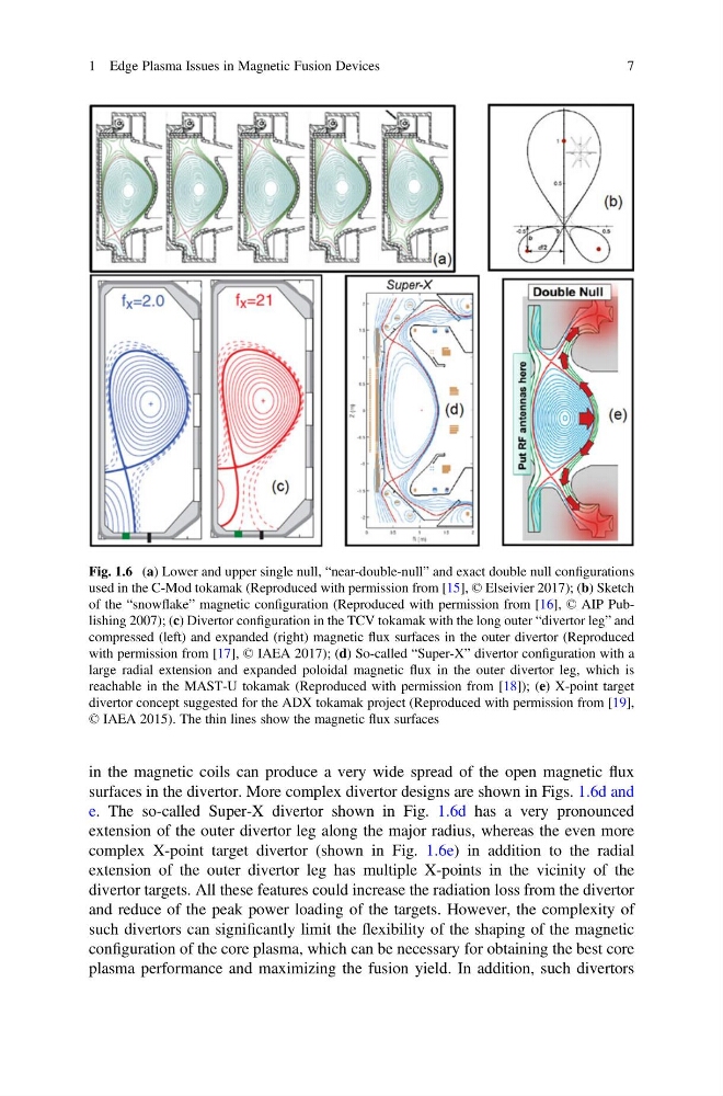
in the magnetic coils can produce a very wide spread of the open magnetic flux
surfaces in the divertor. More complex divertor designs are shown in Figs. 1.6d and
e. The so-called Super-X divertor shown in Fig. 1.6d has a very pronounced
extension of the outer divertor leg along the major radius, whereas the even more
complex X-point target divertor (shown in Fig. 1.6e) in addition to the radial
extension of the outer divertor leg has multiple X-points in the vicinity of the
divertor targets. All these features could increase the radiation loss from the divertor
and reduce of the peak power loading of the targets. However, the complexity of
such divertors can significantly limit the flexibility of the shaping of the magnetic
configuration of the core plasma, which can be necessary for obtaining the best core
plasma performance and maximizing the fusion yield. In addition, such divertors
Fig. 1.6 (a) Lower and upper single null, “near-double-null” and exact double null configurations
used in the C-Mod tokamak (Reproduced with permission from [15], © Elseivier 2017); (b) Sketch
of the “snowflake” magnetic configuration (Reproduced with permission from [16], © AIP Publishing 2007); (c) Divertor configuration in the TCV tokamak with the long outer “divertor leg” and
compressed (left) and expanded (right) magnetic flux surfaces in the outer divertor (Reproduced
with permission from [17], © IAEA 2017); (d) So-called “Super-X” divertor configuration with a
large radial extension and expanded poloidal magnetic flux in the outer divertor leg, which is
reachable in the MAST-U tokamak (Reproduced with permission from [18]); (e) X-point target
divertor concept suggested for the ADX tokamak project (Reproduced with permission from [19],
© IAEA 2015). The thin lines show the magnetic flux surfaces
1 Edge Plasma Issues in Magnetic Fusion Devices
7
surfaces in the divertor. More complex divertor designs are shown in Figs. 1.6d and
e. The so-called Super-X divertor shown in Fig. 1.6d has a very pronounced
extension of the outer divertor leg along the major radius, whereas the even more
complex X-point target divertor (shown in Fig. 1.6e) in addition to the radial
extension of the outer divertor leg has multiple X-points in the vicinity of the
divertor targets. All these features could increase the radiation loss from the divertor
and reduce of the peak power loading of the targets. However, the complexity of
such divertors can significantly limit the flexibility of the shaping of the magnetic
configuration of the core plasma, which can be necessary for obtaining the best core
plasma performance and maximizing the fusion yield. In addition, such divertors
Fig. 1.6 (a) Lower and upper single null, “near-double-null” and exact double null configurations
used in the C-Mod tokamak (Reproduced with permission from [15], © Elseivier 2017); (b) Sketch
of the “snowflake” magnetic configuration (Reproduced with permission from [16], © AIP Publishing 2007); (c) Divertor configuration in the TCV tokamak with the long outer “divertor leg” and
compressed (left) and expanded (right) magnetic flux surfaces in the outer divertor (Reproduced
with permission from [17], © IAEA 2017); (d) So-called “Super-X” divertor configuration with a
large radial extension and expanded poloidal magnetic flux in the outer divertor leg, which is
reachable in the MAST-U tokamak (Reproduced with permission from [18]); (e) X-point target
divertor concept suggested for the ADX tokamak project (Reproduced with permission from [19],
© IAEA 2015). The thin lines show the magnetic flux surfaces
1 Edge Plasma Issues in Magnetic Fusion Devices
7