

For example, in Fig. 1.3b, the so-called “single null” divertor configuration
(having one X-point) is sketched. Apart from this, “double null” divertor configurations, having X-points above and below the core plasma, are used in some
experimental studies. When the double null is exact, only one separatrix separates
the core and both upper and lower divertors. In this case, the outer and inner parts of
the SOL become magnetically disconnected, which has important implications for
anomalous plasma transport in the inner and outer SOL regions. Such a double null
configuration, along with the lower and upper single null and “near-double-null”
configurations used in the C-Mod tokamak are shown in Fig. 1.6a. We notice that the
very first divertors were designed to allow up to 2 X-points in ASDEX and up to
4 X-points in the PDX tokamaks (see Fig. 1.4).
A standard X-point magnetic geometry, which can be formed with just two
effective toroidal currents, has two divertor legs and the strength of the poloidal
magnetic field in the vicinity of the X-point is proportional to the distance to the
X-point, r X . However, with at least three effective toroidal currents, the X-point
could produce four divertor legs and, as a result, reduce the peak heat load on
divertor targets. Such a magnetic configuration can be realized with a “snowflake”
divertor concept (see Fig. 1.6b). In addition, in such a case, the strength of the
poloidal magnetic field in the vicinity of the X-point becomes proportional to r
2
X .
This increases the length of the magnetic field lines in the SOL, and, therefore, could
slow down parallel plasma transport and, therefore, broaden the footprint of the heat
flux on the targets. It also results in an increase of the volume occupied by plasma in
the vicinity of the X-point, which could help to increase the radiation loss from
the divertor.
Magnetic configurations of the TCV tokamak divertor, having a long outer
divertor leg, are shown in Fig. 1.6c. As one can see, manipulation of the currents
Separatrix
ρ (mm)
10
Line averaged density (10 19 m –3 )
2
3
4
5
6
7
–5
10 4
10 5
10 6
10 7
0
5
1 0
detached
951219011@0.739 s
attached
960130036@1.116 s
15
20
20
30
40
50
Density ramp
Inner
divertor
Pulse No’s. 35734,‘35,‘40,‘41,‘43,‘24
J sat Profile at Outer Divertor Surface
J
sat
(A m –2
)
Outer
divertor
Steady state
60
10
20
30
40
50
60
Ion saturation current (Acm –2
)
(a)
(b)
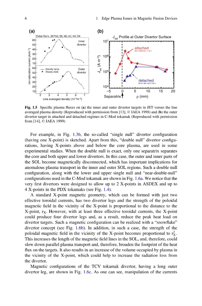
Fig. 1.5 Specific plasma fluxes on (a) the inner and outer divertor targets in JET versus the line
averaged plasma density (Reproduced with permission from [13], © IAEA 1998) and (b) the outer
divertor target in attached and detached regimes in C-Mod tokamak (Reproduced with permission
from [14], © IAEA 1999)
6
1 Edge Plasma Issues in Magnetic Fusion Devices
(having one X-point) is sketched. Apart from this, “double null” divertor configurations, having X-points above and below the core plasma, are used in some
experimental studies. When the double null is exact, only one separatrix separates
the core and both upper and lower divertors. In this case, the outer and inner parts of
the SOL become magnetically disconnected, which has important implications for
anomalous plasma transport in the inner and outer SOL regions. Such a double null
configuration, along with the lower and upper single null and “near-double-null”
configurations used in the C-Mod tokamak are shown in Fig. 1.6a. We notice that the
very first divertors were designed to allow up to 2 X-points in ASDEX and up to
4 X-points in the PDX tokamaks (see Fig. 1.4).
A standard X-point magnetic geometry, which can be formed with just two
effective toroidal currents, has two divertor legs and the strength of the poloidal
magnetic field in the vicinity of the X-point is proportional to the distance to the
X-point, r X . However, with at least three effective toroidal currents, the X-point
could produce four divertor legs and, as a result, reduce the peak heat load on
divertor targets. Such a magnetic configuration can be realized with a “snowflake”
divertor concept (see Fig. 1.6b). In addition, in such a case, the strength of the
poloidal magnetic field in the vicinity of the X-point becomes proportional to r
2
X .
This increases the length of the magnetic field lines in the SOL, and, therefore, could
slow down parallel plasma transport and, therefore, broaden the footprint of the heat
flux on the targets. It also results in an increase of the volume occupied by plasma in
the vicinity of the X-point, which could help to increase the radiation loss from
the divertor.
Magnetic configurations of the TCV tokamak divertor, having a long outer
divertor leg, are shown in Fig. 1.6c. As one can see, manipulation of the currents
Separatrix
ρ (mm)
10
Line averaged density (10 19 m –3 )
2
3
4
5
6
7
–5
10 4
10 5
10 6
10 7
0
5
1 0
detached
951219011@0.739 s
attached
960130036@1.116 s
15
20
20
30
40
50
Density ramp
Inner
divertor
Pulse No’s. 35734,‘35,‘40,‘41,‘43,‘24
J sat Profile at Outer Divertor Surface
J
sat
(A m –2
)
Outer
divertor
Steady state
60
10
20
30
40
50
60
Ion saturation current (Acm –2
)
(a)
(b)
Fig. 1.5 Specific plasma fluxes on (a) the inner and outer divertor targets in JET versus the line
averaged plasma density (Reproduced with permission from [13], © IAEA 1998) and (b) the outer
divertor target in attached and detached regimes in C-Mod tokamak (Reproduced with permission
from [14], © IAEA 1999)
6
1 Edge Plasma Issues in Magnetic Fusion Devices