

7.2 General Solution of the Torsion Problem
225
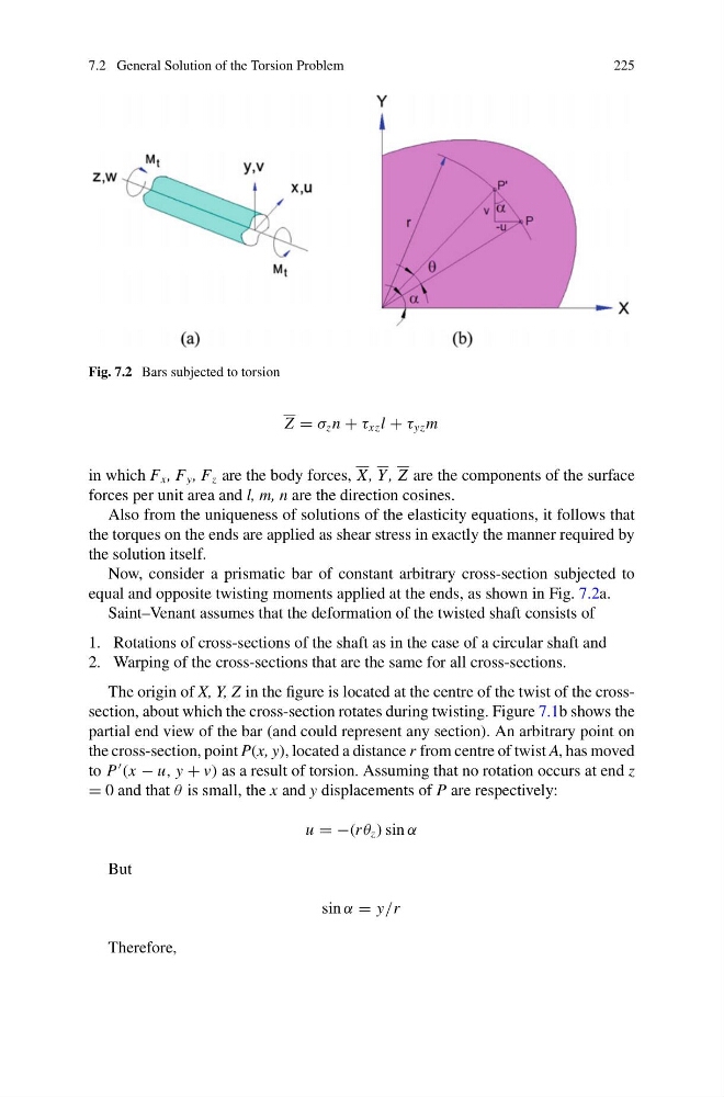
Fig. 7.2 Bars subjected to torsion
Z = σ z n + τ xz l + τ yz m
in which F x , F y , F z are the body forces, X, Y , Z are the components of the surface
forces per unit area and l, m, n are the direction cosines.
Also from the uniqueness of solutions of the elasticity equations, it follows that
the torques on the ends are applied as shear stress in exactly the manner required by
the solution itself.
Now, consider a prismatic bar of constant arbitrary cross-section subjected to
equal and opposite twisting moments applied at the ends, as shown in Fig. 7.2a.
Saint–Venant assumes that the deformation of the twisted shaft consists of
1. Rotations of cross-sections of the shaft as in the case of a circular shaft and
2. Warping of the cross-sections that are the same for all cross-sections.
The origin of X, Y, Z in the figure is located at the centre of the twist of the crosssection, about which the cross-section rotates during twisting. Figure 7.1b shows the
partial end view of the bar (and could represent any section). An arbitrary point on
the cross-section, point P(x, y), located a distance r from centre of twist A, has moved
to P
(x − u, y + v) as a result of torsion. Assuming that no rotation occurs at end z
= 0 and that θ is small, the x and y displacements of P are respectively:
u = −(r θ z ) sin α
But
sin α = y/r
Therefore,
225
Fig. 7.2 Bars subjected to torsion
Z = σ z n + τ xz l + τ yz m
in which F x , F y , F z are the body forces, X, Y , Z are the components of the surface
forces per unit area and l, m, n are the direction cosines.
Also from the uniqueness of solutions of the elasticity equations, it follows that
the torques on the ends are applied as shear stress in exactly the manner required by
the solution itself.
Now, consider a prismatic bar of constant arbitrary cross-section subjected to
equal and opposite twisting moments applied at the ends, as shown in Fig. 7.2a.
Saint–Venant assumes that the deformation of the twisted shaft consists of
1. Rotations of cross-sections of the shaft as in the case of a circular shaft and
2. Warping of the cross-sections that are the same for all cross-sections.
The origin of X, Y, Z in the figure is located at the centre of the twist of the crosssection, about which the cross-section rotates during twisting. Figure 7.1b shows the
partial end view of the bar (and could represent any section). An arbitrary point on
the cross-section, point P(x, y), located a distance r from centre of twist A, has moved
to P
(x − u, y + v) as a result of torsion. Assuming that no rotation occurs at end z
= 0 and that θ is small, the x and y displacements of P are respectively:
u = −(r θ z ) sin α
But
sin α = y/r
Therefore,