

68
3 Subsonic Wind Tunnels
(a) Artist's view
(b) UCAV on a rotating balance
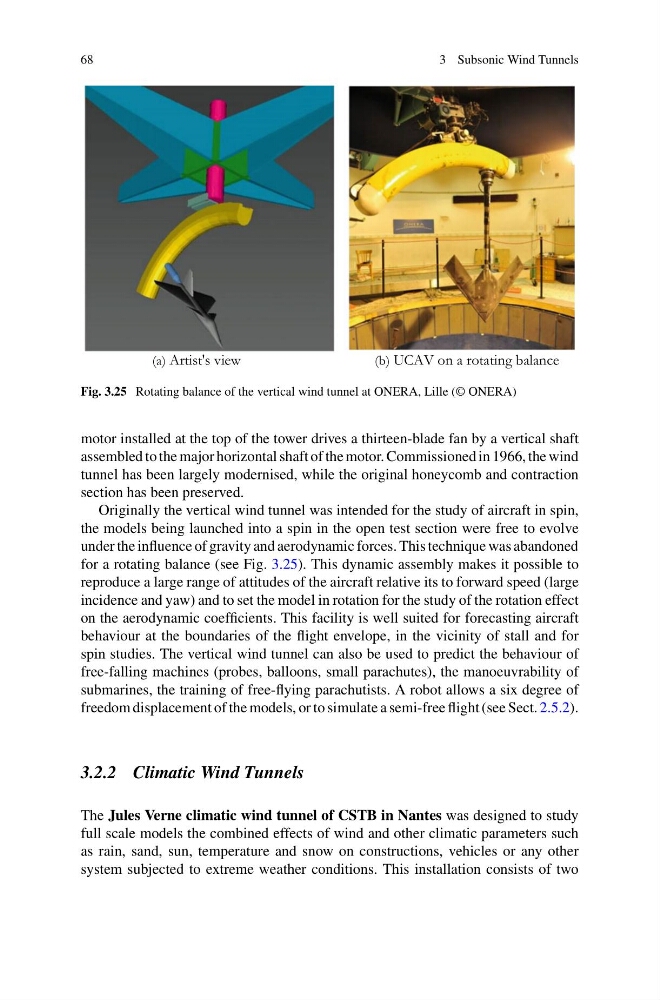
Fig. 3.25 Rotating balance of the vertical wind tunnel at ONERA, Lille (© ONERA)
motor installed at the top of the tower drives a thirteen-blade fan by a vertical shaft
assembled to the major horizontal shaft of the motor. Commissioned in 1966, the wind
tunnel has been largely modernised, while the original honeycomb and contraction
section has been preserved.
Originally the vertical wind tunnel was intended for the study of aircraft in spin,
the models being launched into a spin in the open test section were free to evolve
under the influence of gravity and aerodynamic forces. This technique was abandoned
for a rotating balance (see Fig. 3.25). This dynamic assembly makes it possible to
reproduce a large range of attitudes of the aircraft relative its to forward speed (large
incidence and yaw) and to set the model in rotation for the study of the rotation effect
on the aerodynamic coefficients. This facility is well suited for forecasting aircraft
behaviour at the boundaries of the flight envelope, in the vicinity of stall and for
spin studies. The vertical wind tunnel can also be used to predict the behaviour of
free-falling machines (probes, balloons, small parachutes), the manoeuvrability of
submarines, the training of free-flying parachutists. A robot allows a six degree of
freedom displacement of the models, or to simulate a semi-free flight (see Sect. 2.5.2).
3.2.2 Climatic Wind Tunnels
The Jules Verne climatic wind tunnel of CSTB in Nantes was designed to study
full scale models the combined effects of wind and other climatic parameters such
as rain, sand, sun, temperature and snow on constructions, vehicles or any other
system subjected to extreme weather conditions. This installation consists of two
3 Subsonic Wind Tunnels
(a) Artist's view
(b) UCAV on a rotating balance
Fig. 3.25 Rotating balance of the vertical wind tunnel at ONERA, Lille (© ONERA)
motor installed at the top of the tower drives a thirteen-blade fan by a vertical shaft
assembled to the major horizontal shaft of the motor. Commissioned in 1966, the wind
tunnel has been largely modernised, while the original honeycomb and contraction
section has been preserved.
Originally the vertical wind tunnel was intended for the study of aircraft in spin,
the models being launched into a spin in the open test section were free to evolve
under the influence of gravity and aerodynamic forces. This technique was abandoned
for a rotating balance (see Fig. 3.25). This dynamic assembly makes it possible to
reproduce a large range of attitudes of the aircraft relative its to forward speed (large
incidence and yaw) and to set the model in rotation for the study of the rotation effect
on the aerodynamic coefficients. This facility is well suited for forecasting aircraft
behaviour at the boundaries of the flight envelope, in the vicinity of stall and for
spin studies. The vertical wind tunnel can also be used to predict the behaviour of
free-falling machines (probes, balloons, small parachutes), the manoeuvrability of
submarines, the training of free-flying parachutists. A robot allows a six degree of
freedom displacement of the models, or to simulate a semi-free flight (see Sect. 2.5.2).
3.2.2 Climatic Wind Tunnels
The Jules Verne climatic wind tunnel of CSTB in Nantes was designed to study
full scale models the combined effects of wind and other climatic parameters such
as rain, sand, sun, temperature and snow on constructions, vehicles or any other
system subjected to extreme weather conditions. This installation consists of two