

278
13 Computer-Aided Wind Tunnel Test and Analysis
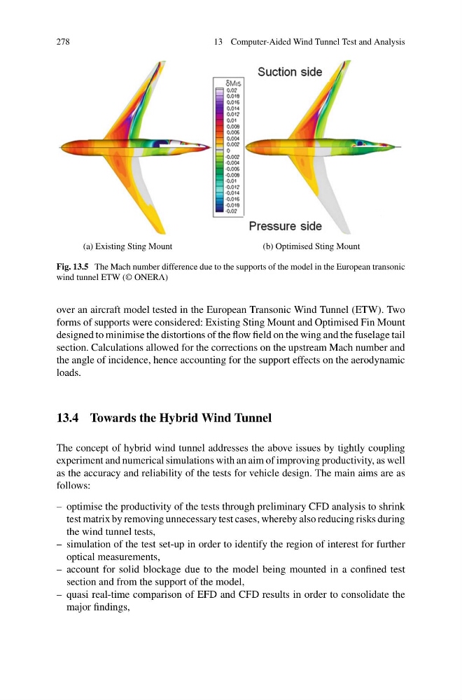
(a) Existing Sting Mount
(b) Optimised Sting Mount
Fig. 13.5 The Mach number difference due to the supports of the model in the European transonic
wind tunnel ETW (© ONERA)
over an aircraft model tested in the European Transonic Wind Tunnel (ETW). Two
forms of supports were considered: Existing Sting Mount and Optimised Fin Mount
designed to minimise the distortions of the flow field on the wing and the fuselage tail
section. Calculations allowed for the corrections on the upstream Mach number and
the angle of incidence, hence accounting for the support effects on the aerodynamic
loads.
13.4 Towards the Hybrid Wind Tunnel
The concept of hybrid wind tunnel addresses the above issues by tightly coupling
experiment and numerical simulations with an aim of improving productivity, as well
as the accuracy and reliability of the tests for vehicle design. The main aims are as
follows:
– optimise the productivity of the tests through preliminary CFD analysis to shrink
test matrix by removing unnecessary test cases, whereby also reducing risks during
the wind tunnel tests,
– simulation of the test set-up in order to identify the region of interest for further
optical measurements,
– account for solid blockage due to the model being mounted in a confined test
section and from the support of the model,
– quasi real-time comparison of EFD and CFD results in order to consolidate the
major findings,
13 Computer-Aided Wind Tunnel Test and Analysis
(a) Existing Sting Mount
(b) Optimised Sting Mount
Fig. 13.5 The Mach number difference due to the supports of the model in the European transonic
wind tunnel ETW (© ONERA)
over an aircraft model tested in the European Transonic Wind Tunnel (ETW). Two
forms of supports were considered: Existing Sting Mount and Optimised Fin Mount
designed to minimise the distortions of the flow field on the wing and the fuselage tail
section. Calculations allowed for the corrections on the upstream Mach number and
the angle of incidence, hence accounting for the support effects on the aerodynamic
loads.
13.4 Towards the Hybrid Wind Tunnel
The concept of hybrid wind tunnel addresses the above issues by tightly coupling
experiment and numerical simulations with an aim of improving productivity, as well
as the accuracy and reliability of the tests for vehicle design. The main aims are as
follows:
– optimise the productivity of the tests through preliminary CFD analysis to shrink
test matrix by removing unnecessary test cases, whereby also reducing risks during
the wind tunnel tests,
– simulation of the test set-up in order to identify the region of interest for further
optical measurements,
– account for solid blockage due to the model being mounted in a confined test
section and from the support of the model,
– quasi real-time comparison of EFD and CFD results in order to consolidate the
major findings,