

8.2 Aerodynamic Balances
195
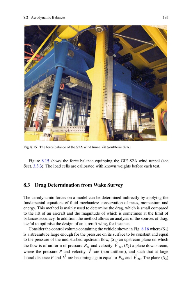
Fig. 8.15 The force balance of the S2A wind tunnel (© Soufflerie S2A)
Figure 8.15 shows the force balance equipping the GIE S2A wind tunnel (see
Sect. 3.3.3). The load cells are calibrated with known weights before each test.
8.3 Drag Determination from Wake Survey
The aerodynamic forces on a model can be determined indirectly by applying the
fundamental equations of fluid mechanics: conservation of mass, momentum and
energy. This method is mainly used to determine the drag, which is small compared
to the lift of an aircraft and the magnitude of which is sometimes at the limit of
balances accuracy. In addition, the method allows an analysis of the sources of drag,
useful to optimise the design of an aircraft wing, for instance.
Consider the control volume containing the vehicle shown in Fig. 8.16 where (S 3 )
is a streamtube large enough for the pressure on its surface to be constant and equal
to the pressure of the undisturbed upstream flow, (S 1 ) an upstream plane on which
the flow is of uniform of pressure P ∞ and velocity
− →
V ∞ , (S 2 ) a plane downstream,
where the pressure P and velocity
− →
V are (non-uniform), and such that at large
lateral distance P and
− →
V are becoming again equal to P ∞ and
− →
V ∞ . The plane (S 2 )
195
Fig. 8.15 The force balance of the S2A wind tunnel (© Soufflerie S2A)
Figure 8.15 shows the force balance equipping the GIE S2A wind tunnel (see
Sect. 3.3.3). The load cells are calibrated with known weights before each test.
8.3 Drag Determination from Wake Survey
The aerodynamic forces on a model can be determined indirectly by applying the
fundamental equations of fluid mechanics: conservation of mass, momentum and
energy. This method is mainly used to determine the drag, which is small compared
to the lift of an aircraft and the magnitude of which is sometimes at the limit of
balances accuracy. In addition, the method allows an analysis of the sources of drag,
useful to optimise the design of an aircraft wing, for instance.
Consider the control volume containing the vehicle shown in Fig. 8.16 where (S 3 )
is a streamtube large enough for the pressure on its surface to be constant and equal
to the pressure of the undisturbed upstream flow, (S 1 ) an upstream plane on which
the flow is of uniform of pressure P ∞ and velocity
− →
V ∞ , (S 2 ) a plane downstream,
where the pressure P and velocity
− →
V are (non-uniform), and such that at large
lateral distance P and
− →
V are becoming again equal to P ∞ and
− →
V ∞ . The plane (S 2 )