

194
8 Measurement of Aerodynamic Forces and Moments
(a) Side view
(b) View from above
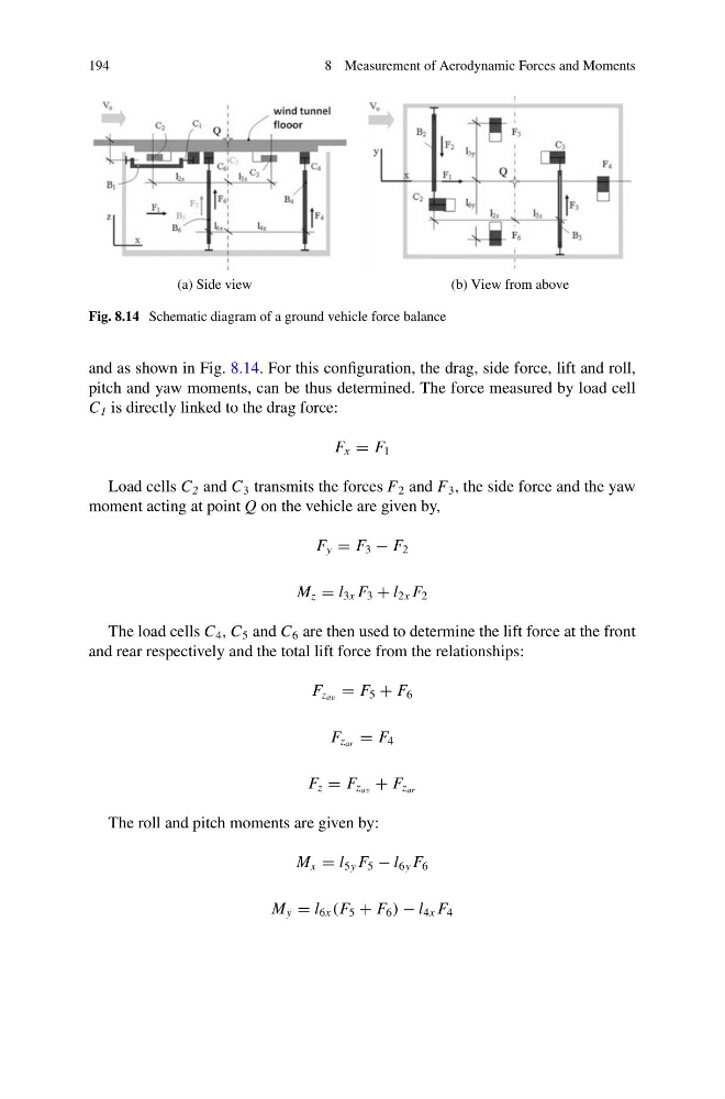
Fig. 8.14 Schematic diagram of a ground vehicle force balance
and as shown in Fig. 8.14. For this configuration, the drag, side force, lift and roll,
pitch and yaw moments, can be thus determined. The force measured by load cell
C 1 is directly linked to the drag force:
F x = F 1
Load cells C 2 and C 3 transmits the forces F 2 and F 3 , the side force and the yaw
moment acting at point Q on the vehicle are given by,
F y = F 3 − F 2
M z = l 3x F 3 + l 2x F 2
The load cells C 4 , C 5 and C 6 are then used to determine the lift force at the front
and rear respectively and the total lift force from the relationships:
F z av = F 5 + F 6
F z ar = F 4
F z = F z av + F z ar
The roll and pitch moments are given by:
M x = l 5y F 5 − l 6y F 6
M y = l 6x (F 5 + F 6 ) − l 4x F 4
8 Measurement of Aerodynamic Forces and Moments
(a) Side view
(b) View from above
Fig. 8.14 Schematic diagram of a ground vehicle force balance
and as shown in Fig. 8.14. For this configuration, the drag, side force, lift and roll,
pitch and yaw moments, can be thus determined. The force measured by load cell
C 1 is directly linked to the drag force:
F x = F 1
Load cells C 2 and C 3 transmits the forces F 2 and F 3 , the side force and the yaw
moment acting at point Q on the vehicle are given by,
F y = F 3 − F 2
M z = l 3x F 3 + l 2x F 2
The load cells C 4 , C 5 and C 6 are then used to determine the lift force at the front
and rear respectively and the total lift force from the relationships:
F z av = F 5 + F 6
F z ar = F 4
F z = F z av + F z ar
The roll and pitch moments are given by:
M x = l 5y F 5 − l 6y F 6
M y = l 6x (F 5 + F 6 ) − l 4x F 4