

8.2 Aerodynamic Balances
193
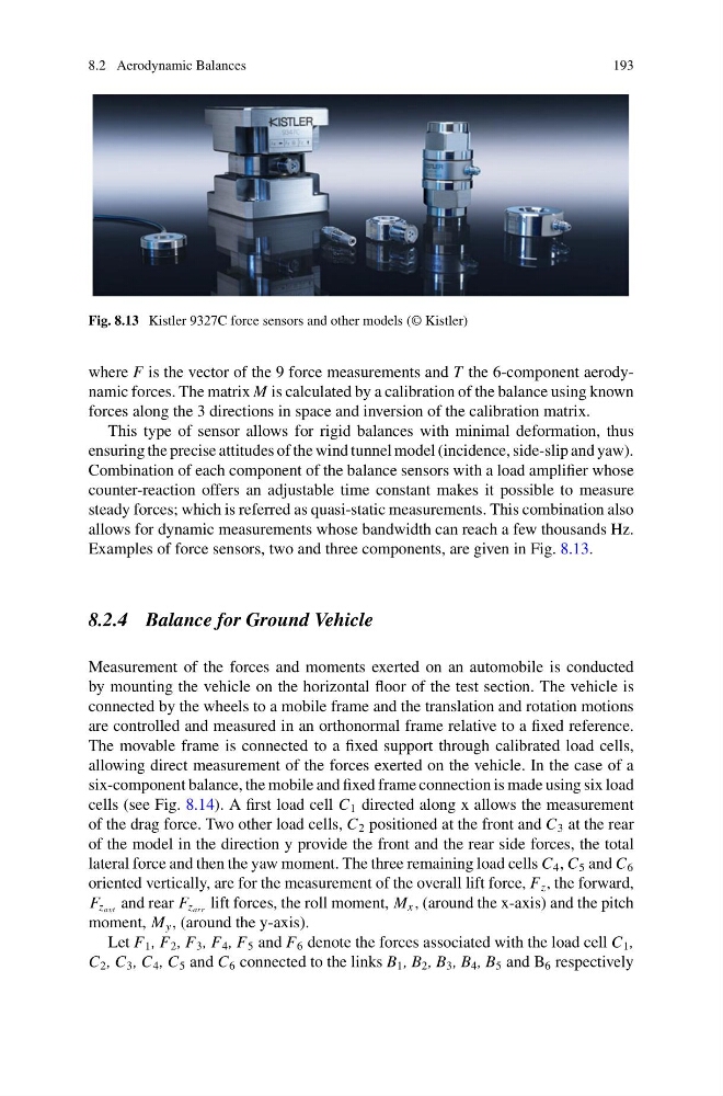
Fig. 8.13 Kistler 9327C force sensors and other models (© Kistler)
where F is the vector of the 9 force measurements and T the 6-component aerodynamic forces. The matrix M is calculated by a calibration of the balance using known
forces along the 3 directions in space and inversion of the calibration matrix.
This type of sensor allows for rigid balances with minimal deformation, thus
ensuring the precise attitudes of the wind tunnel model (incidence, side-slip and yaw).
Combination of each component of the balance sensors with a load amplifier whose
counter-reaction offers an adjustable time constant makes it possible to measure
steady forces; which is referred as quasi-static measurements. This combination also
allows for dynamic measurements whose bandwidth can reach a few thousands Hz.
Examples of force sensors, two and three components, are given in Fig. 8.13.
8.2.4 Balance for Ground Vehicle
Measurement of the forces and moments exerted on an automobile is conducted
by mounting the vehicle on the horizontal floor of the test section. The vehicle is
connected by the wheels to a mobile frame and the translation and rotation motions
are controlled and measured in an orthonormal frame relative to a fixed reference.
The movable frame is connected to a fixed support through calibrated load cells,
allowing direct measurement of the forces exerted on the vehicle. In the case of a
six-component balance, the mobile and fixed frame connection is made using six load
cells (see Fig. 8.14). A first load cell C 1 directed along x allows the measurement
of the drag force. Two other load cells, C 2 positioned at the front and C 3 at the rear
of the model in the direction y provide the front and the rear side forces, the total
lateral force and then the yaw moment. The three remaining load cells C 4 , C 5 and C 6
oriented vertically, are for the measurement of the overall lift force, F z , the forward,
F z avt and rear F z arr lift forces, the roll moment, M x , (around the x-axis) and the pitch
moment, M y , (around the y-axis).
Let F 1 , F 2 , F 3 , F 4 , F 5 and F 6 denote the forces associated with the load cell C 1 ,
C 2 , C 3 , C 4 , C 5 and C 6 connected to the links B 1 , B 2 , B 3 , B 4 , B 5 and B 6 respectively
193
Fig. 8.13 Kistler 9327C force sensors and other models (© Kistler)
where F is the vector of the 9 force measurements and T the 6-component aerodynamic forces. The matrix M is calculated by a calibration of the balance using known
forces along the 3 directions in space and inversion of the calibration matrix.
This type of sensor allows for rigid balances with minimal deformation, thus
ensuring the precise attitudes of the wind tunnel model (incidence, side-slip and yaw).
Combination of each component of the balance sensors with a load amplifier whose
counter-reaction offers an adjustable time constant makes it possible to measure
steady forces; which is referred as quasi-static measurements. This combination also
allows for dynamic measurements whose bandwidth can reach a few thousands Hz.
Examples of force sensors, two and three components, are given in Fig. 8.13.
8.2.4 Balance for Ground Vehicle
Measurement of the forces and moments exerted on an automobile is conducted
by mounting the vehicle on the horizontal floor of the test section. The vehicle is
connected by the wheels to a mobile frame and the translation and rotation motions
are controlled and measured in an orthonormal frame relative to a fixed reference.
The movable frame is connected to a fixed support through calibrated load cells,
allowing direct measurement of the forces exerted on the vehicle. In the case of a
six-component balance, the mobile and fixed frame connection is made using six load
cells (see Fig. 8.14). A first load cell C 1 directed along x allows the measurement
of the drag force. Two other load cells, C 2 positioned at the front and C 3 at the rear
of the model in the direction y provide the front and the rear side forces, the total
lateral force and then the yaw moment. The three remaining load cells C 4 , C 5 and C 6
oriented vertically, are for the measurement of the overall lift force, F z , the forward,
F z avt and rear F z arr lift forces, the roll moment, M x , (around the x-axis) and the pitch
moment, M y , (around the y-axis).
Let F 1 , F 2 , F 3 , F 4 , F 5 and F 6 denote the forces associated with the load cell C 1 ,
C 2 , C 3 , C 4 , C 5 and C 6 connected to the links B 1 , B 2 , B 3 , B 4 , B 5 and B 6 respectively