

196
8 Measurement of Aerodynamic Forces and Moments
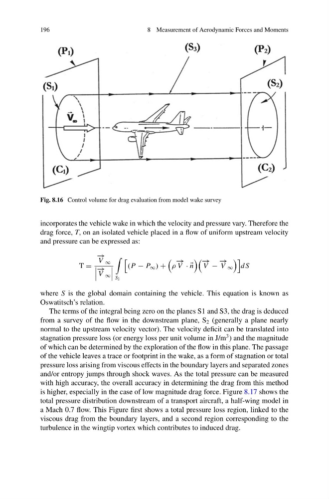
Fig. 8.16 Control volume for drag evaluation from model wake survey
incorporates the vehicle wake in which the velocity and pressure vary. Therefore the
drag force, T, on an isolated vehicle placed in a flow of uniform upstream velocity
and pressure can be expressed as:
T =
− →
V ∞
− →
V ∞
S 2
(P − P ∞ ) +
ρ
− →
V · ·
n
− →
V −
− →
V ∞
d S
where S is the global domain containing the vehicle. This equation is known as
Oswatitsch’s relation.
The terms of the integral being zero on the planes S1 and S3, the drag is deduced
from a survey of the flow in the downstream plane, S 2 (generally a plane nearly
normal to the upstream velocity vector). The velocity deficit can be translated into
stagnation pressure loss (or energy loss per unit volume in J/m
3 ) and the magnitude
of which can be determined by the exploration of the flow in this plane. The passage
of the vehicle leaves a trace or footprint in the wake, as a form of stagnation or total
pressure loss arising from viscous effects in the boundary layers and separated zones
and/or entropy jumps through shock waves. As the total pressure can be measured
with high accuracy, the overall accuracy in determining the drag from this method
is higher, especially in the case of low magnitude drag force. Figure 8.17 shows the
total pressure distribution downstream of a transport aircraft, a half-wing model in
a Mach 0.7 flow. This Figure first shows a total pressure loss region, linked to the
viscous drag from the boundary layers, and a second region corresponding to the
turbulence in the wingtip vortex which contributes to induced drag.
8 Measurement of Aerodynamic Forces and Moments
Fig. 8.16 Control volume for drag evaluation from model wake survey
incorporates the vehicle wake in which the velocity and pressure vary. Therefore the
drag force, T, on an isolated vehicle placed in a flow of uniform upstream velocity
and pressure can be expressed as:
T =
− →
V ∞
− →
V ∞
S 2
(P − P ∞ ) +
ρ
− →
V · ·
n
− →
V −
− →
V ∞
d S
where S is the global domain containing the vehicle. This equation is known as
Oswatitsch’s relation.
The terms of the integral being zero on the planes S1 and S3, the drag is deduced
from a survey of the flow in the downstream plane, S 2 (generally a plane nearly
normal to the upstream velocity vector). The velocity deficit can be translated into
stagnation pressure loss (or energy loss per unit volume in J/m
3 ) and the magnitude
of which can be determined by the exploration of the flow in this plane. The passage
of the vehicle leaves a trace or footprint in the wake, as a form of stagnation or total
pressure loss arising from viscous effects in the boundary layers and separated zones
and/or entropy jumps through shock waves. As the total pressure can be measured
with high accuracy, the overall accuracy in determining the drag from this method
is higher, especially in the case of low magnitude drag force. Figure 8.17 shows the
total pressure distribution downstream of a transport aircraft, a half-wing model in
a Mach 0.7 flow. This Figure first shows a total pressure loss region, linked to the
viscous drag from the boundary layers, and a second region corresponding to the
turbulence in the wingtip vortex which contributes to induced drag.