

6.3 Hypersonic “Hot” or Hyper-enthalpic Wind Tunnels
155
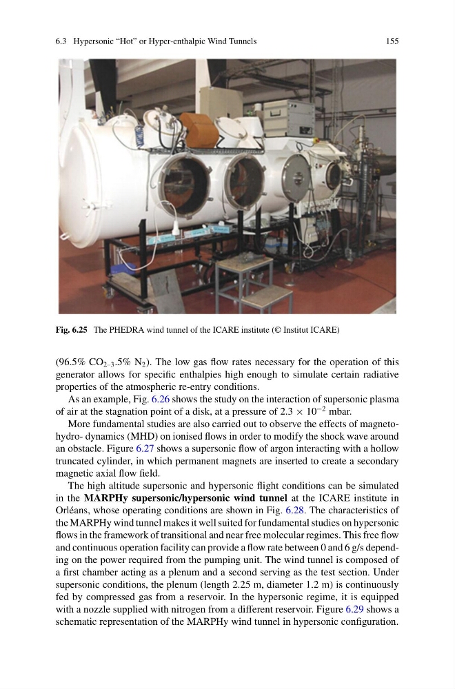
Fig. 6.25 The PHEDRA wind tunnel of the ICARE institute (© Institut ICARE)
(96.5% CO 2–3 .5% N 2 ). The low gas flow rates necessary for the operation of this
generator allows for specific enthalpies high enough to simulate certain radiative
properties of the atmospheric re-entry conditions.
As an example, Fig. 6.26 shows the study on the interaction of supersonic plasma
of air at the stagnation point of a disk, at a pressure of 2.3 × 10
−2 mbar.
More fundamental studies are also carried out to observe the effects of magnetohydro- dynamics (MHD) on ionised flows in order to modify the shock wave around
an obstacle. Figure 6.27 shows a supersonic flow of argon interacting with a hollow
truncated cylinder, in which permanent magnets are inserted to create a secondary
magnetic axial flow field.
The high altitude supersonic and hypersonic flight conditions can be simulated
in the MARPHy supersonic/hypersonic wind tunnel at the ICARE institute in
Orléans, whose operating conditions are shown in Fig. 6.28. The characteristics of
the MARPHy wind tunnel makes it well suited for fundamental studies on hypersonic
flows in the framework of transitional and near free molecular regimes. This free flow
and continuous operation facility can provide a flow rate between 0 and 6 g/s depending on the power required from the pumping unit. The wind tunnel is composed of
a first chamber acting as a plenum and a second serving as the test section. Under
supersonic conditions, the plenum (length 2.25 m, diameter 1.2 m) is continuously
fed by compressed gas from a reservoir. In the hypersonic regime, it is equipped
with a nozzle supplied with nitrogen from a different reservoir. Figure 6.29 shows a
schematic representation of the MARPHy wind tunnel in hypersonic configuration.
155
Fig. 6.25 The PHEDRA wind tunnel of the ICARE institute (© Institut ICARE)
(96.5% CO 2–3 .5% N 2 ). The low gas flow rates necessary for the operation of this
generator allows for specific enthalpies high enough to simulate certain radiative
properties of the atmospheric re-entry conditions.
As an example, Fig. 6.26 shows the study on the interaction of supersonic plasma
of air at the stagnation point of a disk, at a pressure of 2.3 × 10
−2 mbar.
More fundamental studies are also carried out to observe the effects of magnetohydro- dynamics (MHD) on ionised flows in order to modify the shock wave around
an obstacle. Figure 6.27 shows a supersonic flow of argon interacting with a hollow
truncated cylinder, in which permanent magnets are inserted to create a secondary
magnetic axial flow field.
The high altitude supersonic and hypersonic flight conditions can be simulated
in the MARPHy supersonic/hypersonic wind tunnel at the ICARE institute in
Orléans, whose operating conditions are shown in Fig. 6.28. The characteristics of
the MARPHy wind tunnel makes it well suited for fundamental studies on hypersonic
flows in the framework of transitional and near free molecular regimes. This free flow
and continuous operation facility can provide a flow rate between 0 and 6 g/s depending on the power required from the pumping unit. The wind tunnel is composed of
a first chamber acting as a plenum and a second serving as the test section. Under
supersonic conditions, the plenum (length 2.25 m, diameter 1.2 m) is continuously
fed by compressed gas from a reservoir. In the hypersonic regime, it is equipped
with a nozzle supplied with nitrogen from a different reservoir. Figure 6.29 shows a
schematic representation of the MARPHy wind tunnel in hypersonic configuration.