

156
6 Hypersonic Wind Tunnels
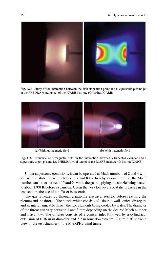
Fig. 6.26 Study of the interaction between the disk stagnation point and a supersonic plasma jet
in the PHEDRA wind tunnel of the ICARE institute (© Institut ICARE)
(a) Without magnetic field
(b) With magnetic field
Fig. 6.27 Influence of a magnetic field on the interaction between a truncated cylinder and a
supersonic argon plasma jet. PHEDRA wind tunnel of the ICARE institute (© Institut ICARE)
Under supersonic conditions, it can be operated at Mach numbers of 2 and 4 with
test section static pressures between 2 and 8 Pa. In a hypersonic regime, the Mach
number can be set between 15 and 20 while the gas supplying the nozzle being heated
to about 1300 K before expansion. Given the very low levels of static pressure in the
test section, the use of a diffuser is essential.
The gas is heated up through a graphite electrical resistor before reaching the
plenum and the throat of the nozzle which consists of a double-wall conical divergent
and an interchangeable throat, the two elements being cooled by water. The diameter
of the throat can vary between 1 and 3 mm depending on the desired Mach number
and mass flow. The diffuser consists of a conical inlet followed by a cylindrical
extension of 0.36 m in diameter and 2.2 m long downstream. Figure 6.30 shows a
view of the test chamber of the MARPHy wind tunnel.
6 Hypersonic Wind Tunnels
Fig. 6.26 Study of the interaction between the disk stagnation point and a supersonic plasma jet
in the PHEDRA wind tunnel of the ICARE institute (© Institut ICARE)
(a) Without magnetic field
(b) With magnetic field
Fig. 6.27 Influence of a magnetic field on the interaction between a truncated cylinder and a
supersonic argon plasma jet. PHEDRA wind tunnel of the ICARE institute (© Institut ICARE)
Under supersonic conditions, it can be operated at Mach numbers of 2 and 4 with
test section static pressures between 2 and 8 Pa. In a hypersonic regime, the Mach
number can be set between 15 and 20 while the gas supplying the nozzle being heated
to about 1300 K before expansion. Given the very low levels of static pressure in the
test section, the use of a diffuser is essential.
The gas is heated up through a graphite electrical resistor before reaching the
plenum and the throat of the nozzle which consists of a double-wall conical divergent
and an interchangeable throat, the two elements being cooled by water. The diameter
of the throat can vary between 1 and 3 mm depending on the desired Mach number
and mass flow. The diffuser consists of a conical inlet followed by a cylindrical
extension of 0.36 m in diameter and 2.2 m long downstream. Figure 6.30 shows a
view of the test chamber of the MARPHy wind tunnel.