

5.4 Mach 6 Quiet Wind Tunnel
133
static air at Mach 4.3 and a Reynolds number of 10 × 10
6 /m. The photo reveals
the acoustic waves radiated by the turbulent structures of the boundary layer on the
lower surface of the cone. These waves propagate according to the Mach angles,
defined from the flow velocity minus the velocity of the boundary-layer disturbances
generating the acoustic waves.
On the upper surface, the boundary layer is intermittent with two clearly visible
turbulent spots immersed in the laminar part. More pronounced waves are visible
in front of the turbulent spots due to the increase in the displacement thickness,
with lower levels of noise radiated by the turbulence inside the spots. Noise is not
present above the laminar regions. This result shows that the control of the laminar
to turbulent transition on the nozzle walls is essential to design facilities for the study
of transition under conditions comparable to those in flight.
The Boeing/AFORS Mach 6 quiet wind tunnel was built at Purdue University to
achieve quiet flows at low hypersonic Mach numbers (high supersonic!) and moderate
Reynolds numbers in “cold” flow; i.e., without simulation of high-speed flow total
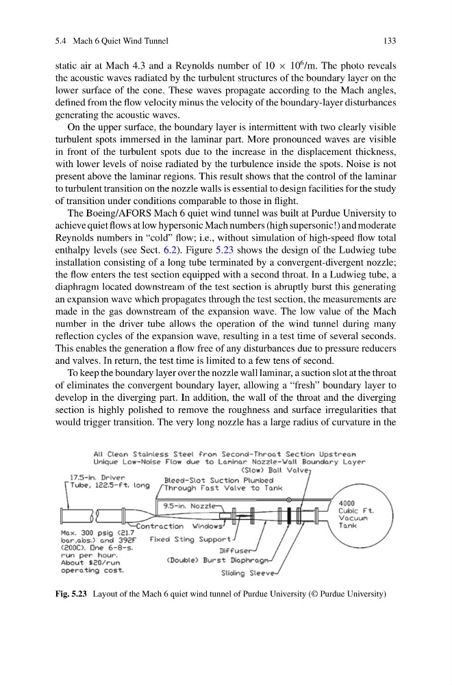
enthalpy levels (see Sect. 6.2). Figure 5.23 shows the design of the Ludwieg tube
installation consisting of a long tube terminated by a convergent-divergent nozzle;
the flow enters the test section equipped with a second throat. In a Ludwieg tube, a
diaphragm located downstream of the test section is abruptly burst this generating
an expansion wave which propagates through the test section, the measurements are
made in the gas downstream of the expansion wave. The low value of the Mach
number in the driver tube allows the operation of the wind tunnel during many
reflection cycles of the expansion wave, resulting in a test time of several seconds.
This enables the generation a flow free of any disturbances due to pressure reducers
and valves. In return, the test time is limited to a few tens of second.
To keep the boundary layer over the nozzle wall laminar, a suction slot at the throat
of eliminates the convergent boundary layer, allowing a “fresh” boundary layer to
develop in the diverging part. In addition, the wall of the throat and the diverging
section is highly polished to remove the roughness and surface irregularities that
would trigger transition. The very long nozzle has a large radius of curvature in the
Fig. 5.23 Layout of the Mach 6 quiet wind tunnel of Purdue University (© Purdue University)
133
static air at Mach 4.3 and a Reynolds number of 10 × 10
6 /m. The photo reveals
the acoustic waves radiated by the turbulent structures of the boundary layer on the
lower surface of the cone. These waves propagate according to the Mach angles,
defined from the flow velocity minus the velocity of the boundary-layer disturbances
generating the acoustic waves.
On the upper surface, the boundary layer is intermittent with two clearly visible
turbulent spots immersed in the laminar part. More pronounced waves are visible
in front of the turbulent spots due to the increase in the displacement thickness,
with lower levels of noise radiated by the turbulence inside the spots. Noise is not
present above the laminar regions. This result shows that the control of the laminar
to turbulent transition on the nozzle walls is essential to design facilities for the study
of transition under conditions comparable to those in flight.
The Boeing/AFORS Mach 6 quiet wind tunnel was built at Purdue University to
achieve quiet flows at low hypersonic Mach numbers (high supersonic!) and moderate
Reynolds numbers in “cold” flow; i.e., without simulation of high-speed flow total
enthalpy levels (see Sect. 6.2). Figure 5.23 shows the design of the Ludwieg tube
installation consisting of a long tube terminated by a convergent-divergent nozzle;
the flow enters the test section equipped with a second throat. In a Ludwieg tube, a
diaphragm located downstream of the test section is abruptly burst this generating
an expansion wave which propagates through the test section, the measurements are
made in the gas downstream of the expansion wave. The low value of the Mach
number in the driver tube allows the operation of the wind tunnel during many
reflection cycles of the expansion wave, resulting in a test time of several seconds.
This enables the generation a flow free of any disturbances due to pressure reducers
and valves. In return, the test time is limited to a few tens of second.
To keep the boundary layer over the nozzle wall laminar, a suction slot at the throat
of eliminates the convergent boundary layer, allowing a “fresh” boundary layer to
develop in the diverging part. In addition, the wall of the throat and the diverging
section is highly polished to remove the roughness and surface irregularities that
would trigger transition. The very long nozzle has a large radius of curvature in the
Fig. 5.23 Layout of the Mach 6 quiet wind tunnel of Purdue University (© Purdue University)