

118
5 Supersonic Wind Tunnels
1. The flow in the throat region is calculated by analytical methods based on the
potential flow equation or by numerical solution of the Euler equations.
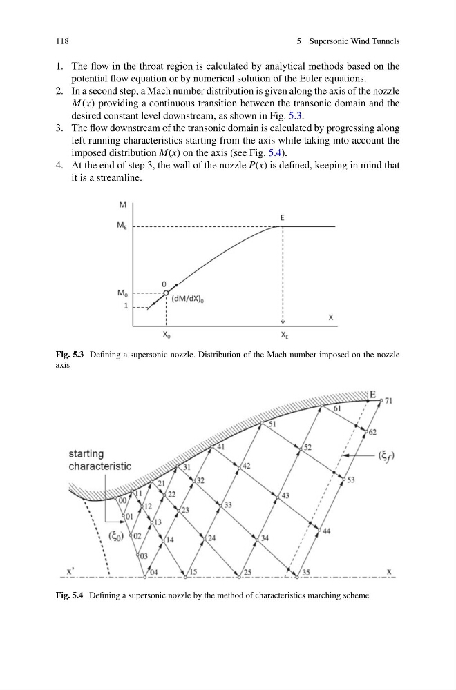
2. In a second step, a Mach number distribution is given along the axis of the nozzle
M(x) providing a continuous transition between the transonic domain and the
desired constant level downstream, as shown in Fig. 5.3.
3. The flow downstream of the transonic domain is calculated by progressing along
left running characteristics starting from the axis while taking into account the
imposed distribution M(x) on the axis (see Fig. 5.4).
4. At the end of step 3, the wall of the nozzle P(x) is defined, keeping in mind that
it is a streamline.
Fig. 5.3 Defining a supersonic nozzle. Distribution of the Mach number imposed on the nozzle
axis
Fig. 5.4 Defining a supersonic nozzle by the method of characteristics marching scheme
5 Supersonic Wind Tunnels
1. The flow in the throat region is calculated by analytical methods based on the
potential flow equation or by numerical solution of the Euler equations.
2. In a second step, a Mach number distribution is given along the axis of the nozzle
M(x) providing a continuous transition between the transonic domain and the
desired constant level downstream, as shown in Fig. 5.3.
3. The flow downstream of the transonic domain is calculated by progressing along
left running characteristics starting from the axis while taking into account the
imposed distribution M(x) on the axis (see Fig. 5.4).
4. At the end of step 3, the wall of the nozzle P(x) is defined, keeping in mind that
it is a streamline.
Fig. 5.3 Defining a supersonic nozzle. Distribution of the Mach number imposed on the nozzle
axis
Fig. 5.4 Defining a supersonic nozzle by the method of characteristics marching scheme