

5.2 Defining of the Contour of a Supersonic Nozzle
119
5. To account for the development of the boundary layer along the nozzle wall, a
boundary layer calculation is performed on P(x), from which the evolution of
the displacement thickness δ*(x) is extracted. The final corrected wall, P final (x),
is obtained by “thickening” P(x) by adding the displacement thickness δ*(x):
P f inal (x) = P(x) + δ
∗
(x)
The boundary layer correction is mandatory for the nozzles in hypersonic wind
tunnels where, due to the high Mach number and the low density, the boundary layer
thickens considerably, occupying a large part of the flow inside the nozzle. This
correction is essential in so-called low-density installations, simulating flows at very
high altitude.
Finally, the contour of the nozzle is defined by a circular arc in the throat region
and a succession of points downstream. The choice of the ratio of the radius of
curvature at the throat and the height (radius) of the throat is critical. A ratio, too
small will lead to the formation of shock waves by focusing of characteristics. A
value of /r c = 4 (or / h c = 4) is a minimum, ratios of at least 10 being adopted
in nozzles for hypersonic wind tunnels.
In the following example, the method is applied to determine the contour of a
planar two-dimensional nozzle to produce a uniform Mach number M o = 2.5 in air
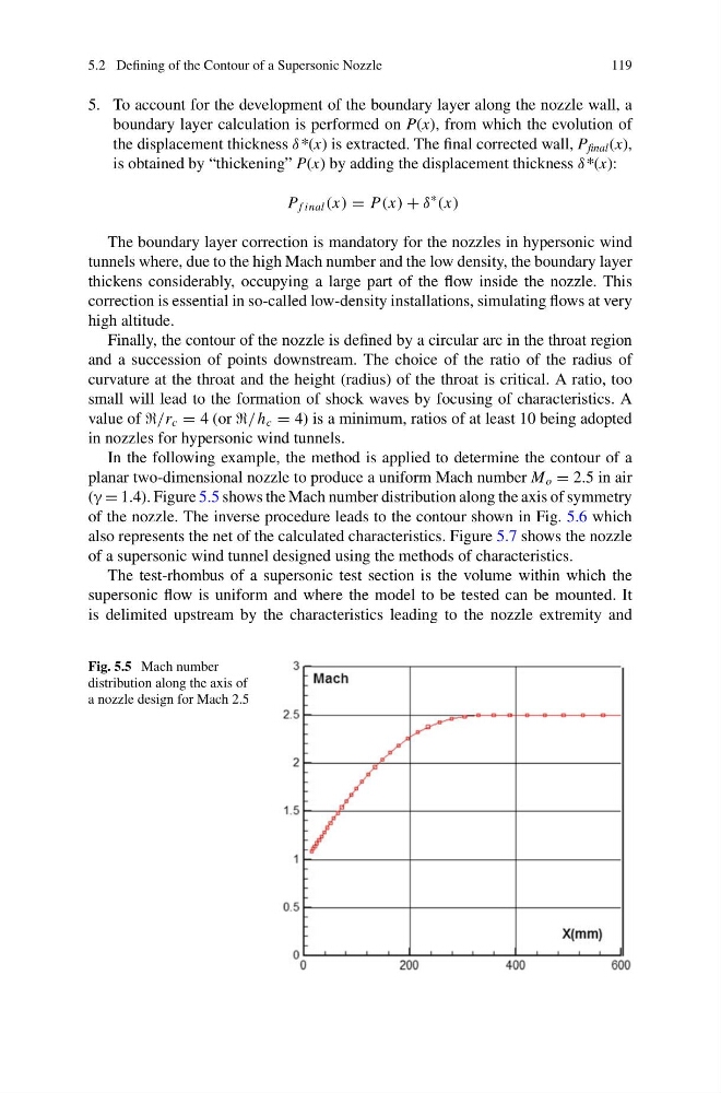
(γ = 1.4). Figure 5.5 shows the Mach number distribution along the axis of symmetry
of the nozzle. The inverse procedure leads to the contour shown in Fig. 5.6 which
also represents the net of the calculated characteristics. Figure 5.7 shows the nozzle
of a supersonic wind tunnel designed using the methods of characteristics.
The test-rhombus of a supersonic test section is the volume within which the
supersonic flow is uniform and where the model to be tested can be mounted. It
is delimited upstream by the characteristics leading to the nozzle extremity and
Fig. 5.5 Mach number
distribution along the axis of
a nozzle design for Mach 2.5
119
5. To account for the development of the boundary layer along the nozzle wall, a
boundary layer calculation is performed on P(x), from which the evolution of
the displacement thickness δ*(x) is extracted. The final corrected wall, P final (x),
is obtained by “thickening” P(x) by adding the displacement thickness δ*(x):
P f inal (x) = P(x) + δ
∗
(x)
The boundary layer correction is mandatory for the nozzles in hypersonic wind
tunnels where, due to the high Mach number and the low density, the boundary layer
thickens considerably, occupying a large part of the flow inside the nozzle. This
correction is essential in so-called low-density installations, simulating flows at very
high altitude.
Finally, the contour of the nozzle is defined by a circular arc in the throat region
and a succession of points downstream. The choice of the ratio of the radius of
curvature at the throat and the height (radius) of the throat is critical. A ratio, too
small will lead to the formation of shock waves by focusing of characteristics. A
value of /r c = 4 (or / h c = 4) is a minimum, ratios of at least 10 being adopted
in nozzles for hypersonic wind tunnels.
In the following example, the method is applied to determine the contour of a
planar two-dimensional nozzle to produce a uniform Mach number M o = 2.5 in air
(γ = 1.4). Figure 5.5 shows the Mach number distribution along the axis of symmetry
of the nozzle. The inverse procedure leads to the contour shown in Fig. 5.6 which
also represents the net of the calculated characteristics. Figure 5.7 shows the nozzle
of a supersonic wind tunnel designed using the methods of characteristics.
The test-rhombus of a supersonic test section is the volume within which the
supersonic flow is uniform and where the model to be tested can be mounted. It
is delimited upstream by the characteristics leading to the nozzle extremity and
Fig. 5.5 Mach number
distribution along the axis of
a nozzle design for Mach 2.5