

3.4 Water Tunnels
93
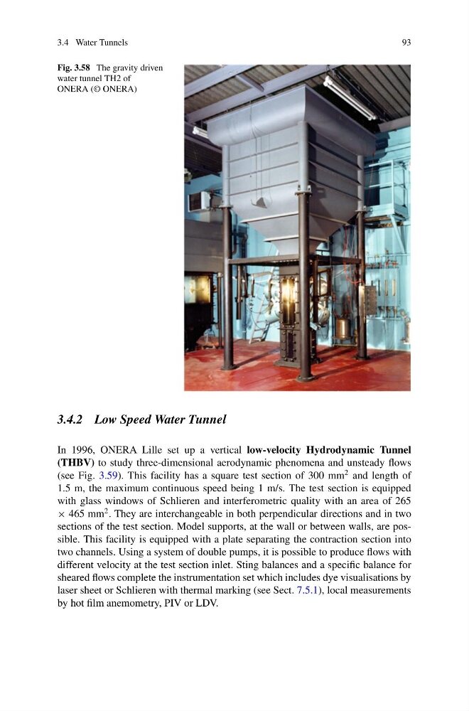
Fig. 3.58 The gravity driven
water tunnel TH2 of
ONERA (© ONERA)
3.4.2 Low Speed Water Tunnel
In 1996, ONERA Lille set up a vertical low-velocity Hydrodynamic Tunnel
(THBV) to study three-dimensional aerodynamic phenomena and unsteady flows
(see Fig. 3.59). This facility has a square test section of 300 mm
2 and length of
1.5 m, the maximum continuous speed being 1 m/s. The test section is equipped
with glass windows of Schlieren and interferometric quality with an area of 265
× 465 mm
2 . They are interchangeable in both perpendicular directions and in two
sections of the test section. Model supports, at the wall or between walls, are possible. This facility is equipped with a plate separating the contraction section into
two channels. Using a system of double pumps, it is possible to produce flows with
different velocity at the test section inlet. Sting balances and a specific balance for
sheared flows complete the instrumentation set which includes dye visualisations by
laser sheet or Schlieren with thermal marking (see Sect. 7.5.1), local measurements
by hot film anemometry, PIV or LDV.
93
Fig. 3.58 The gravity driven
water tunnel TH2 of
ONERA (© ONERA)
3.4.2 Low Speed Water Tunnel
In 1996, ONERA Lille set up a vertical low-velocity Hydrodynamic Tunnel
(THBV) to study three-dimensional aerodynamic phenomena and unsteady flows
(see Fig. 3.59). This facility has a square test section of 300 mm
2 and length of
1.5 m, the maximum continuous speed being 1 m/s. The test section is equipped
with glass windows of Schlieren and interferometric quality with an area of 265
× 465 mm
2 . They are interchangeable in both perpendicular directions and in two
sections of the test section. Model supports, at the wall or between walls, are possible. This facility is equipped with a plate separating the contraction section into
two channels. Using a system of double pumps, it is possible to produce flows with
different velocity at the test section inlet. Sting balances and a specific balance for
sheared flows complete the instrumentation set which includes dye visualisations by
laser sheet or Schlieren with thermal marking (see Sect. 7.5.1), local measurements
by hot film anemometry, PIV or LDV.