

94
3 Subsonic Wind Tunnels
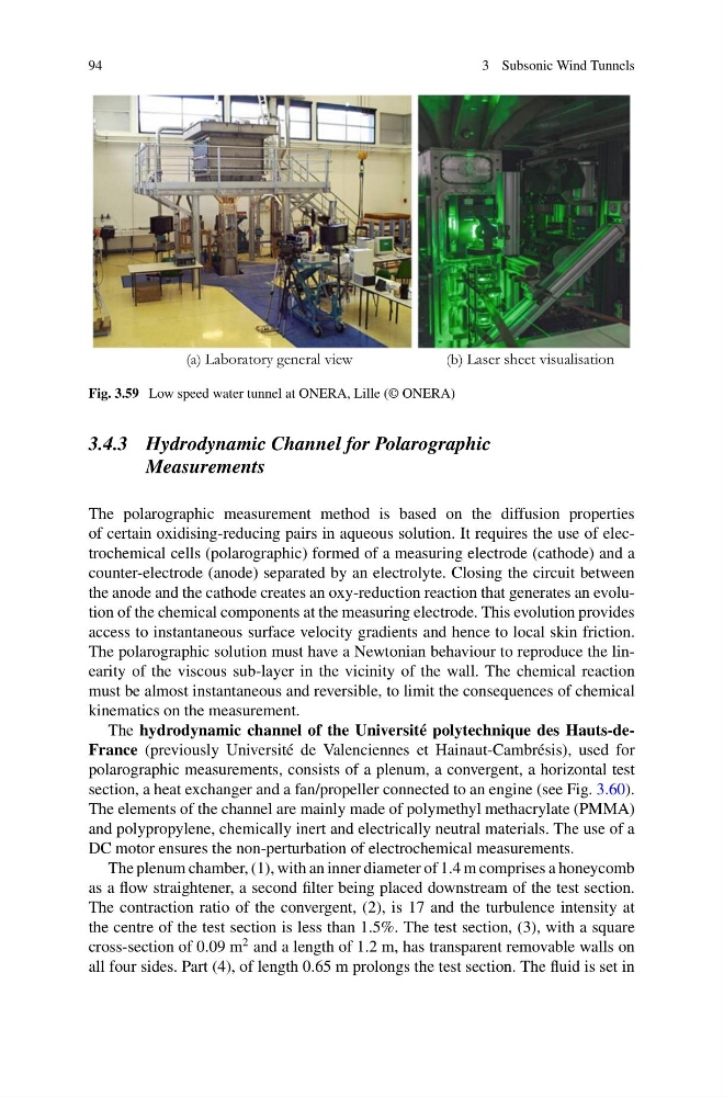
(a) Laboratory general view
(b) Laser sheet visualisation
Fig. 3.59 Low speed water tunnel at ONERA, Lille (© ONERA)
3.4.3 Hydrodynamic Channel for Polarographic
Measurements
The polarographic measurement method is based on the diffusion properties
of certain oxidising-reducing pairs in aqueous solution. It requires the use of electrochemical cells (polarographic) formed of a measuring electrode (cathode) and a
counter-electrode (anode) separated by an electrolyte. Closing the circuit between
the anode and the cathode creates an oxy-reduction reaction that generates an evolution of the chemical components at the measuring electrode. This evolution provides
access to instantaneous surface velocity gradients and hence to local skin friction.
The polarographic solution must have a Newtonian behaviour to reproduce the linearity of the viscous sub-layer in the vicinity of the wall. The chemical reaction
must be almost instantaneous and reversible, to limit the consequences of chemical
kinematics on the measurement.
The hydrodynamic channel of the Université polytechnique des Hauts-deFrance (previously Université de Valenciennes et Hainaut-Cambrésis), used for
polarographic measurements, consists of a plenum, a convergent, a horizontal test
section, a heat exchanger and a fan/propeller connected to an engine (see Fig. 3.60).
The elements of the channel are mainly made of polymethyl methacrylate (PMMA)
and polypropylene, chemically inert and electrically neutral materials. The use of a
DC motor ensures the non-perturbation of electrochemical measurements.
The plenum chamber, (1), with an inner diameter of 1.4 m comprises a honeycomb
as a flow straightener, a second filter being placed downstream of the test section.
The contraction ratio of the convergent, (2), is 17 and the turbulence intensity at
the centre of the test section is less than 1.5%. The test section, (3), with a square
cross-section of 0.09 m
2 and a length of 1.2 m, has transparent removable walls on
all four sides. Part (4), of length 0.65 m prolongs the test section. The fluid is set in
3 Subsonic Wind Tunnels
(a) Laboratory general view
(b) Laser sheet visualisation
Fig. 3.59 Low speed water tunnel at ONERA, Lille (© ONERA)
3.4.3 Hydrodynamic Channel for Polarographic
Measurements
The polarographic measurement method is based on the diffusion properties
of certain oxidising-reducing pairs in aqueous solution. It requires the use of electrochemical cells (polarographic) formed of a measuring electrode (cathode) and a
counter-electrode (anode) separated by an electrolyte. Closing the circuit between
the anode and the cathode creates an oxy-reduction reaction that generates an evolution of the chemical components at the measuring electrode. This evolution provides
access to instantaneous surface velocity gradients and hence to local skin friction.
The polarographic solution must have a Newtonian behaviour to reproduce the linearity of the viscous sub-layer in the vicinity of the wall. The chemical reaction
must be almost instantaneous and reversible, to limit the consequences of chemical
kinematics on the measurement.
The hydrodynamic channel of the Université polytechnique des Hauts-deFrance (previously Université de Valenciennes et Hainaut-Cambrésis), used for
polarographic measurements, consists of a plenum, a convergent, a horizontal test
section, a heat exchanger and a fan/propeller connected to an engine (see Fig. 3.60).
The elements of the channel are mainly made of polymethyl methacrylate (PMMA)
and polypropylene, chemically inert and electrically neutral materials. The use of a
DC motor ensures the non-perturbation of electrochemical measurements.
The plenum chamber, (1), with an inner diameter of 1.4 m comprises a honeycomb
as a flow straightener, a second filter being placed downstream of the test section.
The contraction ratio of the convergent, (2), is 17 and the turbulence intensity at
the centre of the test section is less than 1.5%. The test section, (3), with a square
cross-section of 0.09 m
2 and a length of 1.2 m, has transparent removable walls on
all four sides. Part (4), of length 0.65 m prolongs the test section. The fluid is set in