

7 Application of CR-39 Solid State Nuclear Track Detectors …
137
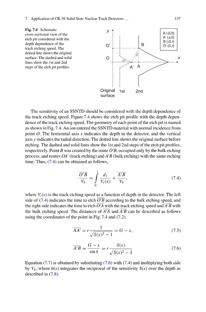
Fig. 7.4 Schematic
cross-sectional view of the
etch pit considered with the
depth dependence of the
track etching speed. The
dotted line shows the original
surface. The dashed and solid
lines show the 1st and 2nd
steps of the etch pit profiles
The sensitivity of an SSNTD should be considered with the depth dependence of
the track etching speed. Figure 7.4 shows the etch pit profile with the depth dependence of the track etching speed. The geometry of each point of the etch pit is named
as shown in Fig. 7.4. An ion entered the SSNTD material with normal incidence from
point O. The horizontal axis x indicates the depth in the detector, and the vertical
axis y indicates the radial direction. The dotted line shows the original surface before
etching. The dashed and solid lines show the 1st and 2nd steps of the etch pit profiles,
respectively. Point B was created by the route O
B, occupied only by the bulk etching
process, and routes OA
(track etching) and A
B (bulk etching) with the same etching
time. Thus, (7.4) can be obtained as follows,
O B
V b
=
x
0
d x
V t (x)
+
A B
V b
,
(7.4)
where V t (x) is the track etching speed as a function of depth in the detector. The left
side of (7.4) indicates the time to etch O B according to the bulk etching speed, and
the right side indicates the time to etch O A with the track etching speed and A B with
the bulk etching speed. The distances of A A and A B can be described as follows
using the coordinates of the point in Fig. 7.4 and (7.2).
A A = r
1
S(x) 2 − 1
= G − x,
(7.5)
A B =
G − x
sin δ
= r
S(x)
S(x) 2 − 1
(7.6)
Equation (7.7) is obtained by substituting (7.6) with (7.4) and multiplying both side
by V b , where h(x) integrates the reciprocal of the sensitivity S(x) over the depth as
described in (7.8).
137
Fig. 7.4 Schematic
cross-sectional view of the
etch pit considered with the
depth dependence of the
track etching speed. The
dotted line shows the original
surface. The dashed and solid
lines show the 1st and 2nd
steps of the etch pit profiles
The sensitivity of an SSNTD should be considered with the depth dependence of
the track etching speed. Figure 7.4 shows the etch pit profile with the depth dependence of the track etching speed. The geometry of each point of the etch pit is named
as shown in Fig. 7.4. An ion entered the SSNTD material with normal incidence from
point O. The horizontal axis x indicates the depth in the detector, and the vertical
axis y indicates the radial direction. The dotted line shows the original surface before
etching. The dashed and solid lines show the 1st and 2nd steps of the etch pit profiles,
respectively. Point B was created by the route O
B, occupied only by the bulk etching
process, and routes OA
(track etching) and A
B (bulk etching) with the same etching
time. Thus, (7.4) can be obtained as follows,
O B
V b
=
x
0
d x
V t (x)
+
A B
V b
,
(7.4)
where V t (x) is the track etching speed as a function of depth in the detector. The left
side of (7.4) indicates the time to etch O B according to the bulk etching speed, and
the right side indicates the time to etch O A with the track etching speed and A B with
the bulk etching speed. The distances of A A and A B can be described as follows
using the coordinates of the point in Fig. 7.4 and (7.2).
A A = r
1
S(x) 2 − 1
= G − x,
(7.5)
A B =
G − x
sin δ
= r
S(x)
S(x) 2 − 1
(7.6)
Equation (7.7) is obtained by substituting (7.6) with (7.4) and multiplying both side
by V b , where h(x) integrates the reciprocal of the sensitivity S(x) over the depth as
described in (7.8).