

136
M. Kanasaki et al.
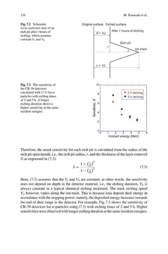
Fig. 7.2 Schematic
cross-sectional view of an
etch pit after t hours of
etching, which assumes
constant V t and V b
Fig. 7.3 The sensitivity of
the CR-39 detectors
calculated with (7.3) for α
particles with etching times
of 2 and 5 h. A longer
etching duration shows a
higher sensitivity at the same
incident energies
Therefore, the usual sensitivity for each etch pit is calculated from the radius of the
etch pit open mouth, i.e., the etch pit radius, r, and the thickness of the layer removed
G as expressed in (7.3).
S =
1 +
r
G
2
1 −
r
G
2
(7.3)
Here, (7.3) assumes that the V t and V b are constant; in other words, the sensitivity
does not depend on depth in the detector material, i.e., the etching duration. V b is
always constant in a typical chemical etching treatment. The track etching speed
V t , however, varies along the ion track. This is because ions deposit their energy in
accordance with the stopping power; namely, the deposited energy increases towards
the end of their range in the detector. For example, Fig. 7.3 shows the sensitivity of
CR-39 detectors for α-particles using (7.3) with etching times of 2 and 5 h. Higher
sensitivities were observed with longer etching duration at the same incident energies.
M. Kanasaki et al.
Fig. 7.2 Schematic
cross-sectional view of an
etch pit after t hours of
etching, which assumes
constant V t and V b
Fig. 7.3 The sensitivity of
the CR-39 detectors
calculated with (7.3) for α
particles with etching times
of 2 and 5 h. A longer
etching duration shows a
higher sensitivity at the same
incident energies
Therefore, the usual sensitivity for each etch pit is calculated from the radius of the
etch pit open mouth, i.e., the etch pit radius, r, and the thickness of the layer removed
G as expressed in (7.3).
S =
1 +
r
G
2
1 −
r
G
2
(7.3)
Here, (7.3) assumes that the V t and V b are constant; in other words, the sensitivity
does not depend on depth in the detector material, i.e., the etching duration. V b is
always constant in a typical chemical etching treatment. The track etching speed
V t , however, varies along the ion track. This is because ions deposit their energy in
accordance with the stopping power; namely, the deposited energy increases towards
the end of their range in the detector. For example, Fig. 7.3 shows the sensitivity of
CR-39 detectors for α-particles using (7.3) with etching times of 2 and 5 h. Higher
sensitivities were observed with longer etching duration at the same incident energies.