

170
L. Lin et al.
bottom. Its density decreases after heating, so the vapor rises along the heating tube
into the separation chamber. In a vacuum and suddenly expanding state, the water
in the solution evaporates rapidly. The solution becomes more condensate and has a
high density. It then enters the heating chamber through the connection pipe, draining
the hotter, lighter solution into the separation chamber. This process is repeated as
above.
Since the solution circulates fast in this evaporator, the overall production efficiency is better than the other two evaporators mentioned above, and it is also easy
to wash. Therefore, it is widely adopted by glycerol factories.
However, when processing thermally unstable substances like glycerol, if they
stay in the heating zone for an excessive amount of time, there will be negative
impacts on the end products, which is the main disadvantage of this evaporator. In
particular, in cases where the concentrated glycerol has been refined by ion-exchange
resins, this disadvantage stands out. This is because this refinement process can
produce products better than common distilled glycerol. If they are treated by the
above three evaporators, their quality may be affected. Centrifugal evaporator and
membrane rotary evaporator can reduce the time required for the evaporation process
and minimize thermal conversion of the production.
➁ Auxiliary equipment for vacuum evaporation
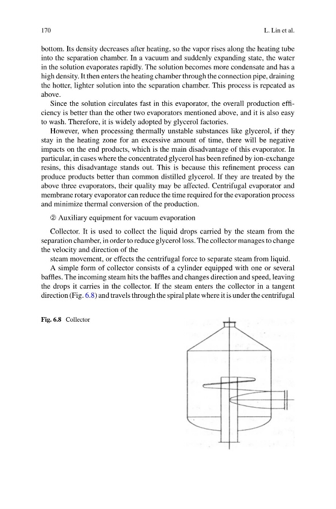
Collector. It is used to collect the liquid drops carried by the steam from the
separation chamber, in order to reduce glycerol loss. The collector manages to change
the velocity and direction of the
steam movement, or effects the centrifugal force to separate steam from liquid.
A simple form of collector consists of a cylinder equipped with one or several
baffles. The incoming steam hits the baffles and changes direction and speed, leaving
the drops it carries in the collector. If the steam enters the collector in a tangent
direction (Fig. 6.8) and travels through the spiral plate where it is under the centrifugal
Fig. 6.8 Collector
L. Lin et al.
bottom. Its density decreases after heating, so the vapor rises along the heating tube
into the separation chamber. In a vacuum and suddenly expanding state, the water
in the solution evaporates rapidly. The solution becomes more condensate and has a
high density. It then enters the heating chamber through the connection pipe, draining
the hotter, lighter solution into the separation chamber. This process is repeated as
above.
Since the solution circulates fast in this evaporator, the overall production efficiency is better than the other two evaporators mentioned above, and it is also easy
to wash. Therefore, it is widely adopted by glycerol factories.
However, when processing thermally unstable substances like glycerol, if they
stay in the heating zone for an excessive amount of time, there will be negative
impacts on the end products, which is the main disadvantage of this evaporator. In
particular, in cases where the concentrated glycerol has been refined by ion-exchange
resins, this disadvantage stands out. This is because this refinement process can
produce products better than common distilled glycerol. If they are treated by the
above three evaporators, their quality may be affected. Centrifugal evaporator and
membrane rotary evaporator can reduce the time required for the evaporation process
and minimize thermal conversion of the production.
➁ Auxiliary equipment for vacuum evaporation
Collector. It is used to collect the liquid drops carried by the steam from the
separation chamber, in order to reduce glycerol loss. The collector manages to change
the velocity and direction of the
steam movement, or effects the centrifugal force to separate steam from liquid.
A simple form of collector consists of a cylinder equipped with one or several
baffles. The incoming steam hits the baffles and changes direction and speed, leaving
the drops it carries in the collector. If the steam enters the collector in a tangent
direction (Fig. 6.8) and travels through the spiral plate where it is under the centrifugal
Fig. 6.8 Collector