

720
7 Countermeasures Against Hardware Trojans
The protected microcircuit also contains a PUF, which generates random bits
based on uncontrollable process variations that are unique to each chip. After poweron, a certain set of tests is supplied to the inputs of the chip source. PUF response is
sent to the triggers implementing BSFM. Since there are K” = log{|S’| +|S|} triggers
total in the BSFM, correct operation of the microcircuit will require K” bits of PUF
response accordingly.
After IC power-on, original values of the triggers (the so-called power-on state)
are determined by the unique response generated by the PUF block on each chip.
Main PUF tasks are determined by the test vectors formed by the chip developer.
In order to ensure safe PUF design, the possibility of response shall be equally
distributed across the entire possible range of values [122]. The number of triggers
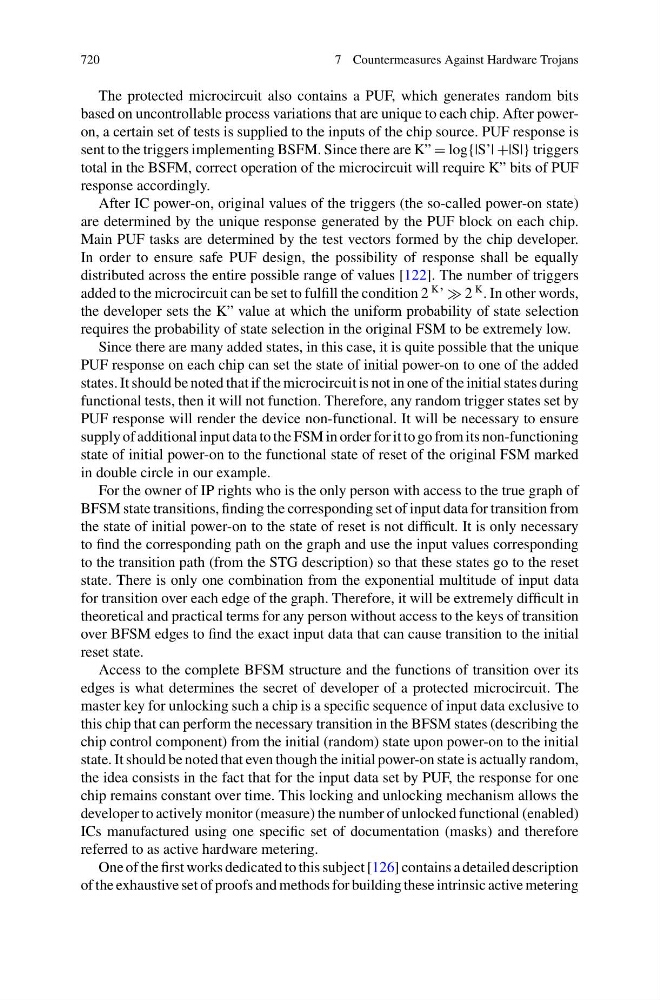
added to the microcircuit can be set to fulfill the condition 2
K ’ 2
K . In other words,
the developer sets the K” value at which the uniform probability of state selection
requires the probability of state selection in the original FSM to be extremely low.
Since there are many added states, in this case, it is quite possible that the unique
PUF response on each chip can set the state of initial power-on to one of the added
states. It should be noted that if the microcircuit is not in one of the initial states during
functional tests, then it will not function. Therefore, any random trigger states set by
PUF response will render the device non-functional. It will be necessary to ensure
supply of additional input data to the FSM in order for it to go from its non-functioning
state of initial power-on to the functional state of reset of the original FSM marked
in double circle in our example.
For the owner of IP rights who is the only person with access to the true graph of
BFSM state transitions, finding the corresponding set of input data for transition from
the state of initial power-on to the state of reset is not difficult. It is only necessary
to find the corresponding path on the graph and use the input values corresponding
to the transition path (from the STG description) so that these states go to the reset
state. There is only one combination from the exponential multitude of input data
for transition over each edge of the graph. Therefore, it will be extremely difficult in
theoretical and practical terms for any person without access to the keys of transition
over BFSM edges to find the exact input data that can cause transition to the initial
reset state.
Access to the complete BFSM structure and the functions of transition over its
edges is what determines the secret of developer of a protected microcircuit. The
master key for unlocking such a chip is a specific sequence of input data exclusive to
this chip that can perform the necessary transition in the BFSM states (describing the
chip control component) from the initial (random) state upon power-on to the initial
state. It should be noted that even though the initial power-on state is actually random,
the idea consists in the fact that for the input data set by PUF, the response for one
chip remains constant over time. This locking and unlocking mechanism allows the
developer to actively monitor (measure) the number of unlocked functional (enabled)
ICs manufactured using one specific set of documentation (masks) and therefore
referred to as active hardware metering.
One of the first works dedicated to this subject [126] contains a detailed description
of the exhaustive set of proofs and methods for building these intrinsic active metering