

610
6 Reverse Engineering of Microcircuits
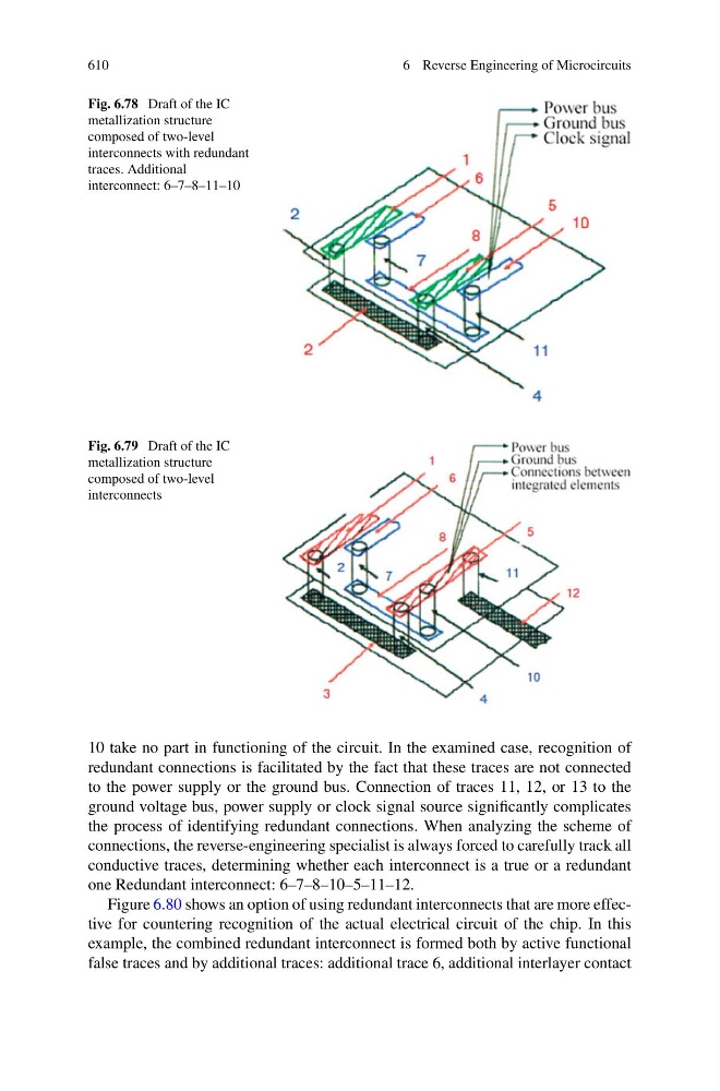
Fig. 6.78 Draft of the IC
metallization structure
composed of two-level
interconnects with redundant
traces. Additional
interconnect: 6–7–8–11–10
Fig. 6.79 Draft of the IC
metallization structure
composed of two-level
interconnects
10 take no part in functioning of the circuit. In the examined case, recognition of
redundant connections is facilitated by the fact that these traces are not connected
to the power supply or the ground bus. Connection of traces 11, 12, or 13 to the
ground voltage bus, power supply or clock signal source significantly complicates
the process of identifying redundant connections. When analyzing the scheme of
connections, the reverse-engineering specialist is always forced to carefully track all
conductive traces, determining whether each interconnect is a true or a redundant
one Redundant interconnect: 6–7–8–10–5–11–12.
Figure 6.80 shows an option of using redundant interconnects that are more effective for countering recognition of the actual electrical circuit of the chip. In this
example, the combined redundant interconnect is formed both by active functional
false traces and by additional traces: additional trace 6, additional interlayer contact
6 Reverse Engineering of Microcircuits
Fig. 6.78 Draft of the IC
metallization structure
composed of two-level
interconnects with redundant
traces. Additional
interconnect: 6–7–8–11–10
Fig. 6.79 Draft of the IC
metallization structure
composed of two-level
interconnects
10 take no part in functioning of the circuit. In the examined case, recognition of
redundant connections is facilitated by the fact that these traces are not connected
to the power supply or the ground bus. Connection of traces 11, 12, or 13 to the
ground voltage bus, power supply or clock signal source significantly complicates
the process of identifying redundant connections. When analyzing the scheme of
connections, the reverse-engineering specialist is always forced to carefully track all
conductive traces, determining whether each interconnect is a true or a redundant
one Redundant interconnect: 6–7–8–10–5–11–12.
Figure 6.80 shows an option of using redundant interconnects that are more effective for countering recognition of the actual electrical circuit of the chip. In this
example, the combined redundant interconnect is formed both by active functional
false traces and by additional traces: additional trace 6, additional interlayer contact