

6.7 Methods of Counteracting Microcircuit Re-engineering Processes
609
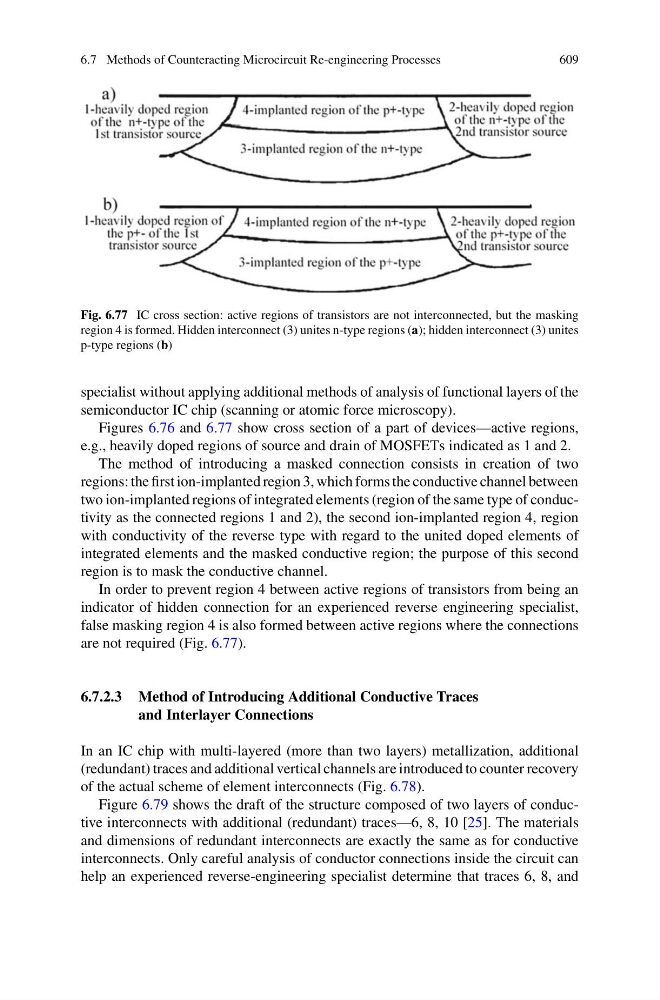
Fig. 6.77 IC cross section: active regions of transistors are not interconnected, but the masking
region 4 is formed. Hidden interconnect (3) unites n-type regions (a); hidden interconnect (3) unites
p-type regions (b)
specialist without applying additional methods of analysis of functional layers of the
semiconductor IC chip (scanning or atomic force microscopy).
Figures 6.76 and 6.77 show cross section of a part of devices—active regions,
e.g., heavily doped regions of source and drain of MOSFETs indicated as 1 and 2.
The method of introducing a masked connection consists in creation of two
regions: the first ion-implanted region 3, which forms the conductive channel between
two ion-implanted regions of integrated elements (region of the same type of conductivity as the connected regions 1 and 2), the second ion-implanted region 4, region
with conductivity of the reverse type with regard to the united doped elements of
integrated elements and the masked conductive region; the purpose of this second
region is to mask the conductive channel.
In order to prevent region 4 between active regions of transistors from being an
indicator of hidden connection for an experienced reverse engineering specialist,
false masking region 4 is also formed between active regions where the connections
are not required (Fig. 6.77).
6.7.2.3 Method of Introducing Additional Conductive Traces
and Interlayer Connections
In an IC chip with multi-layered (more than two layers) metallization, additional
(redundant) traces and additional vertical channels are introduced to counter recovery
of the actual scheme of element interconnects (Fig. 6.78).
Figure 6.79 shows the draft of the structure composed of two layers of conductive interconnects with additional (redundant) traces—6, 8, 10 [25]. The materials
and dimensions of redundant interconnects are exactly the same as for conductive
interconnects. Only careful analysis of conductor connections inside the circuit can
help an experienced reverse-engineering specialist determine that traces 6, 8, and
609
Fig. 6.77 IC cross section: active regions of transistors are not interconnected, but the masking
region 4 is formed. Hidden interconnect (3) unites n-type regions (a); hidden interconnect (3) unites
p-type regions (b)
specialist without applying additional methods of analysis of functional layers of the
semiconductor IC chip (scanning or atomic force microscopy).
Figures 6.76 and 6.77 show cross section of a part of devices—active regions,
e.g., heavily doped regions of source and drain of MOSFETs indicated as 1 and 2.
The method of introducing a masked connection consists in creation of two
regions: the first ion-implanted region 3, which forms the conductive channel between
two ion-implanted regions of integrated elements (region of the same type of conductivity as the connected regions 1 and 2), the second ion-implanted region 4, region
with conductivity of the reverse type with regard to the united doped elements of
integrated elements and the masked conductive region; the purpose of this second
region is to mask the conductive channel.
In order to prevent region 4 between active regions of transistors from being an
indicator of hidden connection for an experienced reverse engineering specialist,
false masking region 4 is also formed between active regions where the connections
are not required (Fig. 6.77).
6.7.2.3 Method of Introducing Additional Conductive Traces
and Interlayer Connections
In an IC chip with multi-layered (more than two layers) metallization, additional
(redundant) traces and additional vertical channels are introduced to counter recovery
of the actual scheme of element interconnects (Fig. 6.78).
Figure 6.79 shows the draft of the structure composed of two layers of conductive interconnects with additional (redundant) traces—6, 8, 10 [25]. The materials
and dimensions of redundant interconnects are exactly the same as for conductive
interconnects. Only careful analysis of conductor connections inside the circuit can
help an experienced reverse-engineering specialist determine that traces 6, 8, and