

580
6 Reverse Engineering of Microcircuits
– Have different vector colors for each topology layer and region: for example, transistor gates are characterized by green rectangles, first metallization layer—by red
rectangles, and the contacts between polysilicon layer and the first metallization
layer—by blue rectangles;
– Be introduced taking into account possible overlapping of a topology element
with switching buses.
It is also necessary to consider that the rectangles characterizing light regions are
more resistant to most common noises and distortions of the image: passing of the
conductor over the element, presence of scratches, and preparation defects.
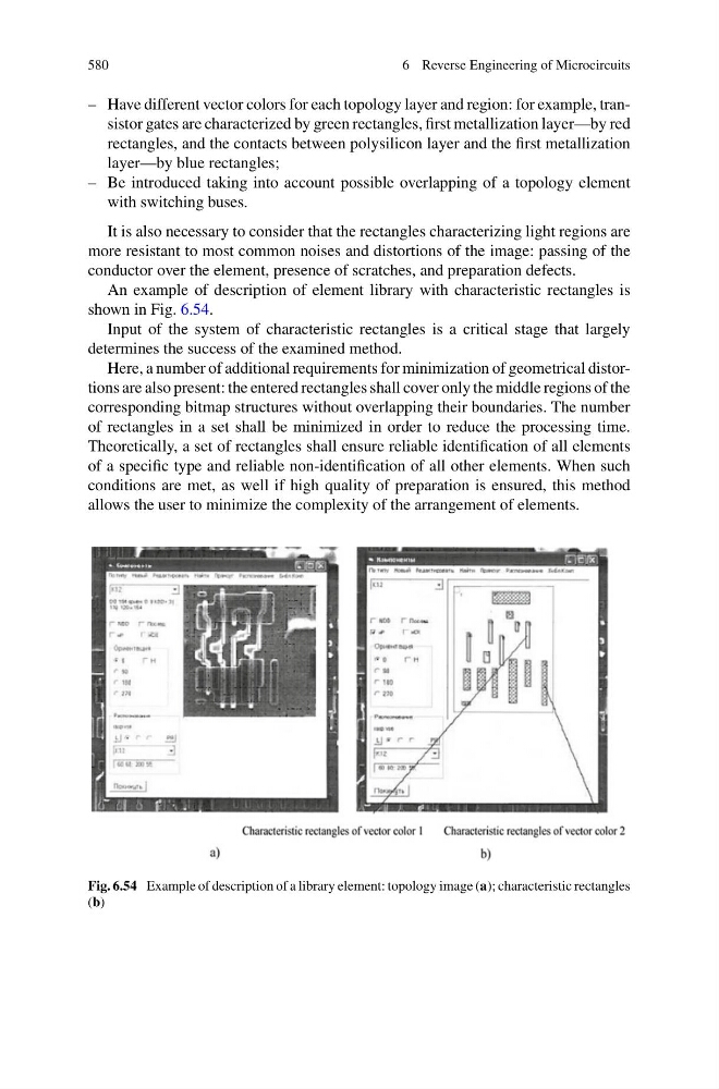
An example of description of element library with characteristic rectangles is
shown in Fig. 6.54.
Input of the system of characteristic rectangles is a critical stage that largely
determines the success of the examined method.
Here, a number of additional requirements for minimization of geometrical distortions are also present: the entered rectangles shall cover only the middle regions of the
corresponding bitmap structures without overlapping their boundaries. The number
of rectangles in a set shall be minimized in order to reduce the processing time.
Theoretically, a set of rectangles shall ensure reliable identification of all elements
of a specific type and reliable non-identification of all other elements. When such
conditions are met, as well if high quality of preparation is ensured, this method
allows the user to minimize the complexity of the arrangement of elements.
Fig. 6.54 Example of description of a library element: topology image (a); characteristic rectangles
(b)
6 Reverse Engineering of Microcircuits
– Have different vector colors for each topology layer and region: for example, transistor gates are characterized by green rectangles, first metallization layer—by red
rectangles, and the contacts between polysilicon layer and the first metallization
layer—by blue rectangles;
– Be introduced taking into account possible overlapping of a topology element
with switching buses.
It is also necessary to consider that the rectangles characterizing light regions are
more resistant to most common noises and distortions of the image: passing of the
conductor over the element, presence of scratches, and preparation defects.
An example of description of element library with characteristic rectangles is
shown in Fig. 6.54.
Input of the system of characteristic rectangles is a critical stage that largely
determines the success of the examined method.
Here, a number of additional requirements for minimization of geometrical distortions are also present: the entered rectangles shall cover only the middle regions of the
corresponding bitmap structures without overlapping their boundaries. The number
of rectangles in a set shall be minimized in order to reduce the processing time.
Theoretically, a set of rectangles shall ensure reliable identification of all elements
of a specific type and reliable non-identification of all other elements. When such
conditions are met, as well if high quality of preparation is ensured, this method
allows the user to minimize the complexity of the arrangement of elements.
Fig. 6.54 Example of description of a library element: topology image (a); characteristic rectangles
(b)