

6.5 Methods for Restoring Electrical Circuit …
581
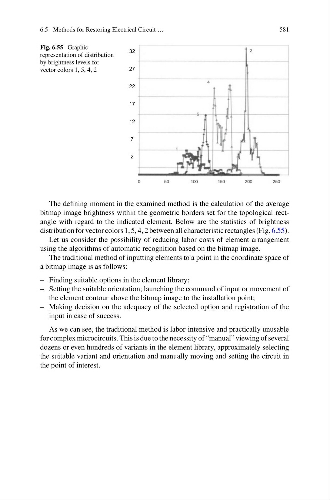
Fig. 6.55 Graphic
representation of distribution
by brightness levels for
vector colors 1, 5, 4, 2
The defining moment in the examined method is the calculation of the average
bitmap image brightness within the geometric borders set for the topological rectangle with regard to the indicated element. Below are the statistics of brightness
distribution for vector colors 1, 5, 4, 2 between all characteristic rectangles (Fig. 6.55).
Let us consider the possibility of reducing labor costs of element arrangement
using the algorithms of automatic recognition based on the bitmap image.
The traditional method of inputting elements to a point in the coordinate space of
a bitmap image is as follows:
– Finding suitable options in the element library;
– Setting the suitable orientation; launching the command of input or movement of
the element contour above the bitmap image to the installation point;
– Making decision on the adequacy of the selected option and registration of the
input in case of success.
As we can see, the traditional method is labor-intensive and practically unusable
for complex microcircuits. This is due to the necessity of “manual” viewing of several
dozens or even hundreds of variants in the element library, approximately selecting
the suitable variant and orientation and manually moving and setting the circuit in
the point of interest.
581
Fig. 6.55 Graphic
representation of distribution
by brightness levels for
vector colors 1, 5, 4, 2
The defining moment in the examined method is the calculation of the average
bitmap image brightness within the geometric borders set for the topological rectangle with regard to the indicated element. Below are the statistics of brightness
distribution for vector colors 1, 5, 4, 2 between all characteristic rectangles (Fig. 6.55).
Let us consider the possibility of reducing labor costs of element arrangement
using the algorithms of automatic recognition based on the bitmap image.
The traditional method of inputting elements to a point in the coordinate space of
a bitmap image is as follows:
– Finding suitable options in the element library;
– Setting the suitable orientation; launching the command of input or movement of
the element contour above the bitmap image to the installation point;
– Making decision on the adequacy of the selected option and registration of the
input in case of success.
As we can see, the traditional method is labor-intensive and practically unusable
for complex microcircuits. This is due to the necessity of “manual” viewing of several
dozens or even hundreds of variants in the element library, approximately selecting
the suitable variant and orientation and manually moving and setting the circuit in
the point of interest.