

5.4 Specific Examples from the Experience of Belarusian Trojan Hunters
495
During testing, the image of the wafer is projected into the plane of a high-speed
linear CCD camera which converts the image into digital form; after that, the image is
saved in memory. Similar sections of images of adjacent chips or cells are compared
to each other in sequence; if the comparison difference exceeds the threshold set
in advance, they are registered as potential discrepancies. After that, attribution of
discrepancies to the same object is determined, the size of the detected defect is
defined, and the decision on its registration is made.
Testing in the light-field mode is performed under illumination in a wide spectral range (450–650 nm), which significantly reduces the quantity of false defects
connected with interference phenomena in thin films.
Control process
A cassette with tested wafers with a diameter of 100 or 150 mm is installed in the
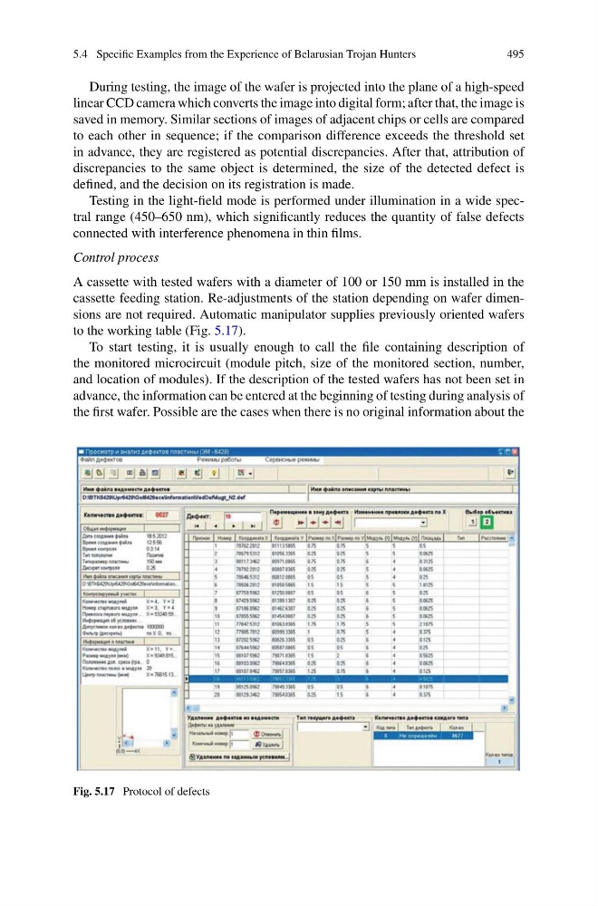
cassette feeding station. Re-adjustments of the station depending on wafer dimensions are not required. Automatic manipulator supplies previously oriented wafers
to the working table (Fig. 5.17).
To start testing, it is usually enough to call the file containing description of
the monitored microcircuit (module pitch, size of the monitored section, number,
and location of modules). If the description of the tested wafers has not been set in
advance, the information can be entered at the beginning of testing during analysis of
the first wafer. Possible are the cases when there is no original information about the
Fig. 5.17 Protocol of defects
495
During testing, the image of the wafer is projected into the plane of a high-speed
linear CCD camera which converts the image into digital form; after that, the image is
saved in memory. Similar sections of images of adjacent chips or cells are compared
to each other in sequence; if the comparison difference exceeds the threshold set
in advance, they are registered as potential discrepancies. After that, attribution of
discrepancies to the same object is determined, the size of the detected defect is
defined, and the decision on its registration is made.
Testing in the light-field mode is performed under illumination in a wide spectral range (450–650 nm), which significantly reduces the quantity of false defects
connected with interference phenomena in thin films.
Control process
A cassette with tested wafers with a diameter of 100 or 150 mm is installed in the
cassette feeding station. Re-adjustments of the station depending on wafer dimensions are not required. Automatic manipulator supplies previously oriented wafers
to the working table (Fig. 5.17).
To start testing, it is usually enough to call the file containing description of
the monitored microcircuit (module pitch, size of the monitored section, number,
and location of modules). If the description of the tested wafers has not been set in
advance, the information can be entered at the beginning of testing during analysis of
the first wafer. Possible are the cases when there is no original information about the
Fig. 5.17 Protocol of defects