

4.10 Techniques for Hardware Trojan Design
411
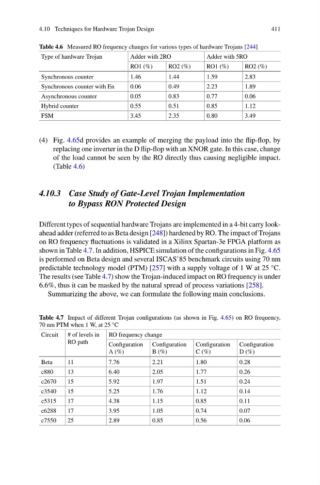
Table 4.6 Measured RO frequency changes for various types of hardware Trojans [244]
Type of hardware Trojan
Adder with 2RO
Adder with 5RO
RO1 (%)
RO2 (%)
RO1 (%)
RO2 (%)
Synchronous counter
1.46
1.44
1.59
2.83
Synchronous counter with En
0.06
0.49
2.23
1.89
Asynchronous counter
0.05
0.83
0.77
0.06
Hybrid counter
0.55
0.51
0.85
1.12
FSM
3.45
2.35
0.80
3.49
(4) Fig. 4.65d provides an example of merging the payload into the flip-flop, by
replacing one inverter in the D flip-flop with an XNOR gate. In this case, change
of the load cannot be seen by the RO directly thus causing negligible impact.
(Table 4.6)
4.10.3 Case Study of Gate-Level Trojan Implementation
to Bypass RON Protected Design
Different types of sequential hardware Trojans are implemented in a 4-bit carry lookahead adder (referred to as Beta design [248]) hardened by RO. The impact of Trojans
on RO frequency fluctuations is validated in a Xilinx Spartan-3e FPGA platform as
shown in Table 4.7. In addition, HSPICE simulation of the configurations in Fig. 4.65
is performed on Beta design and several ISCAS’85 benchmark circuits using 70 nm
predictable technology model (PTM) [257] with a supply voltage of 1 W at 25 °C.
The results (see Table 4.7) show the Trojan-induced impact on RO frequency is under
6.6%, thus it can be masked by the natural spread of process variations [258].
Summarizing the above, we can formulate the following main conclusions.
Table 4.7 Impact of different Trojan configurations (as shown in Fig. 4.65) on RO frequency,
70 nm PTM when 1 W, at 25 °C
Circuit
# of levels in
RO path
RO frequency change
Configuration
A (%)
Configuration
B (%)
Configuration
C (%)
Configuration
D (%)
Beta
11
7.76
2.21
1.80
0.28
c880
13
6.40
2.05
1.77
0.26
c2670
15
5.92
1.97
1.51
0.24
c3540
15
5.25
1.76
1.12
0.14
c5315
17
4.38
1.15
0.85
0.11
c6288
17
3.95
1.05
0.74
0.07
c7550
25
2.89
0.85
0.56
0.06
411
Table 4.6 Measured RO frequency changes for various types of hardware Trojans [244]
Type of hardware Trojan
Adder with 2RO
Adder with 5RO
RO1 (%)
RO2 (%)
RO1 (%)
RO2 (%)
Synchronous counter
1.46
1.44
1.59
2.83
Synchronous counter with En
0.06
0.49
2.23
1.89
Asynchronous counter
0.05
0.83
0.77
0.06
Hybrid counter
0.55
0.51
0.85
1.12
FSM
3.45
2.35
0.80
3.49
(4) Fig. 4.65d provides an example of merging the payload into the flip-flop, by
replacing one inverter in the D flip-flop with an XNOR gate. In this case, change
of the load cannot be seen by the RO directly thus causing negligible impact.
(Table 4.6)
4.10.3 Case Study of Gate-Level Trojan Implementation
to Bypass RON Protected Design
Different types of sequential hardware Trojans are implemented in a 4-bit carry lookahead adder (referred to as Beta design [248]) hardened by RO. The impact of Trojans
on RO frequency fluctuations is validated in a Xilinx Spartan-3e FPGA platform as
shown in Table 4.7. In addition, HSPICE simulation of the configurations in Fig. 4.65
is performed on Beta design and several ISCAS’85 benchmark circuits using 70 nm
predictable technology model (PTM) [257] with a supply voltage of 1 W at 25 °C.
The results (see Table 4.7) show the Trojan-induced impact on RO frequency is under
6.6%, thus it can be masked by the natural spread of process variations [258].
Summarizing the above, we can formulate the following main conclusions.
Table 4.7 Impact of different Trojan configurations (as shown in Fig. 4.65) on RO frequency,
70 nm PTM when 1 W, at 25 °C
Circuit
# of levels in
RO path
RO frequency change
Configuration
A (%)
Configuration
B (%)
Configuration
C (%)
Configuration
D (%)
Beta
11
7.76
2.21
1.80
0.28
c880
13
6.40
2.05
1.77
0.26
c2670
15
5.92
1.97
1.51
0.24
c3540
15
5.25
1.76
1.12
0.14
c5315
17
4.38
1.15
0.85
0.11
c6288
17
3.95
1.05
0.74
0.07
c7550
25
2.89
0.85
0.56
0.06