

410
4 Hardware Trojans in Microcircuits
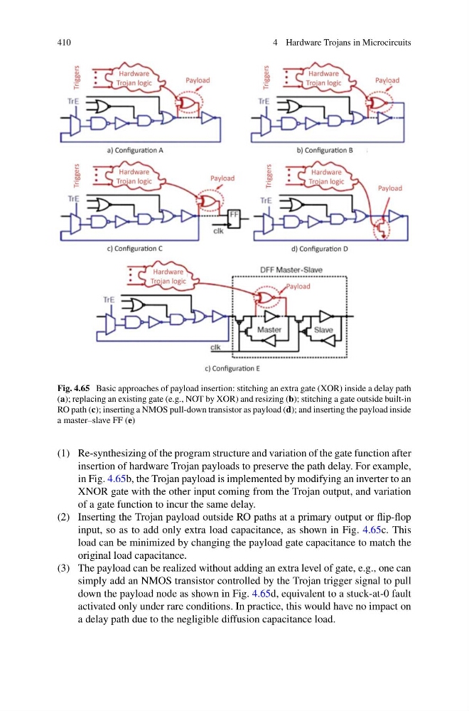
Fig. 4.65 Basic approaches of payload insertion: stitching an extra gate (XOR) inside a delay path
(a); replacing an existing gate (e.g., NOT by XOR) and resizing (b); stitching a gate outside built-in
RO path (c); inserting a NMOS pull-down transistor as payload (d); and inserting the payload inside
a master–slave FF (e)
(1) Re-synthesizing of the program structure and variation of the gate function after
insertion of hardware Trojan payloads to preserve the path delay. For example,
in Fig. 4.65b, the Trojan payload is implemented by modifying an inverter to an
XNOR gate with the other input coming from the Trojan output, and variation
of a gate function to incur the same delay.
(2) Inserting the Trojan payload outside RO paths at a primary output or flip-flop
input, so as to add only extra load capacitance, as shown in Fig. 4.65c. This
load can be minimized by changing the payload gate capacitance to match the
original load capacitance.
(3) The payload can be realized without adding an extra level of gate, e.g., one can
simply add an NMOS transistor controlled by the Trojan trigger signal to pull
down the payload node as shown in Fig. 4.65d, equivalent to a stuck-at-0 fault
activated only under rare conditions. In practice, this would have no impact on
a delay path due to the negligible diffusion capacitance load.
4 Hardware Trojans in Microcircuits
Fig. 4.65 Basic approaches of payload insertion: stitching an extra gate (XOR) inside a delay path
(a); replacing an existing gate (e.g., NOT by XOR) and resizing (b); stitching a gate outside built-in
RO path (c); inserting a NMOS pull-down transistor as payload (d); and inserting the payload inside
a master–slave FF (e)
(1) Re-synthesizing of the program structure and variation of the gate function after
insertion of hardware Trojan payloads to preserve the path delay. For example,
in Fig. 4.65b, the Trojan payload is implemented by modifying an inverter to an
XNOR gate with the other input coming from the Trojan output, and variation
of a gate function to incur the same delay.
(2) Inserting the Trojan payload outside RO paths at a primary output or flip-flop
input, so as to add only extra load capacitance, as shown in Fig. 4.65c. This
load can be minimized by changing the payload gate capacitance to match the
original load capacitance.
(3) The payload can be realized without adding an extra level of gate, e.g., one can
simply add an NMOS transistor controlled by the Trojan trigger signal to pull
down the payload node as shown in Fig. 4.65d, equivalent to a stuck-at-0 fault
activated only under rare conditions. In practice, this would have no impact on
a delay path due to the negligible diffusion capacitance load.