

Simulations of Machining Processes at Small …
251
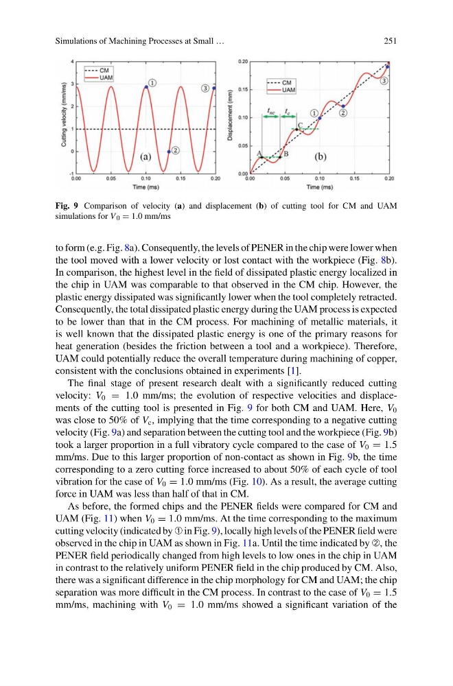
Fig. 9 Comparison of velocity (a) and displacement (b) of cutting tool for CM and UAM
simulations for V 0 = 1.0 mm/ms
to form (e.g. Fig. 8a). Consequently, the levels of PENER in the chip were lower when
the tool moved with a lower velocity or lost contact with the workpiece (Fig. 8b).
In comparison, the highest level in the field of dissipated plastic energy localized in
the chip in UAM was comparable to that observed in the CM chip. However, the
plastic energy dissipated was significantly lower when the tool completely retracted.
Consequently, the total dissipated plastic energy during the UAM process is expected
to be lower than that in the CM process. For machining of metallic materials, it
is well known that the dissipated plastic energy is one of the primary reasons for
heat generation (besides the friction between a tool and a workpiece). Therefore,
UAM could potentially reduce the overall temperature during machining of copper,
consistent with the conclusions obtained in experiments [1].
The final stage of present research dealt with a significantly reduced cutting
velocity: V 0 = 1.0 mm/ms; the evolution of respective velocities and displacements of the cutting tool is presented in Fig. 9 for both CM and UAM. Here, V 0
was close to 50% of V c , implying that the time corresponding to a negative cutting
velocity (Fig. 9a) and separation between the cutting tool and the workpiece (Fig. 9b)
took a larger proportion in a full vibratory cycle compared to the case of V 0 = 1.5
mm/ms. Due to this larger proportion of non-contact as shown in Fig. 9b, the time
corresponding to a zero cutting force increased to about 50% of each cycle of tool
vibration for the case of V 0 = 1.0 mm/ms (Fig. 10). As a result, the average cutting
force in UAM was less than half of that in CM.
As before, the formed chips and the PENER fields were compared for CM and
UAM (Fig. 11) when V 0 = 1.0 mm/ms. At the time corresponding to the maximum
cutting velocity (indicated by ➀ in Fig. 9), locally high levels of the PENER field were
observed in the chip in UAM as shown in Fig. 11a. Until the time indicated by ➁, the
PENER field periodically changed from high levels to low ones in the chip in UAM
in contrast to the relatively uniform PENER field in the chip produced by CM. Also,
there was a significant difference in the chip morphology for CM and UAM; the chip
separation was more difficult in the CM process. In contrast to the case of V 0 = 1.5
mm/ms, machining with V 0 = 1.0 mm/ms showed a significant variation of the
251
Fig. 9 Comparison of velocity (a) and displacement (b) of cutting tool for CM and UAM
simulations for V 0 = 1.0 mm/ms
to form (e.g. Fig. 8a). Consequently, the levels of PENER in the chip were lower when
the tool moved with a lower velocity or lost contact with the workpiece (Fig. 8b).
In comparison, the highest level in the field of dissipated plastic energy localized in
the chip in UAM was comparable to that observed in the CM chip. However, the
plastic energy dissipated was significantly lower when the tool completely retracted.
Consequently, the total dissipated plastic energy during the UAM process is expected
to be lower than that in the CM process. For machining of metallic materials, it
is well known that the dissipated plastic energy is one of the primary reasons for
heat generation (besides the friction between a tool and a workpiece). Therefore,
UAM could potentially reduce the overall temperature during machining of copper,
consistent with the conclusions obtained in experiments [1].
The final stage of present research dealt with a significantly reduced cutting
velocity: V 0 = 1.0 mm/ms; the evolution of respective velocities and displacements of the cutting tool is presented in Fig. 9 for both CM and UAM. Here, V 0
was close to 50% of V c , implying that the time corresponding to a negative cutting
velocity (Fig. 9a) and separation between the cutting tool and the workpiece (Fig. 9b)
took a larger proportion in a full vibratory cycle compared to the case of V 0 = 1.5
mm/ms. Due to this larger proportion of non-contact as shown in Fig. 9b, the time
corresponding to a zero cutting force increased to about 50% of each cycle of tool
vibration for the case of V 0 = 1.0 mm/ms (Fig. 10). As a result, the average cutting
force in UAM was less than half of that in CM.
As before, the formed chips and the PENER fields were compared for CM and
UAM (Fig. 11) when V 0 = 1.0 mm/ms. At the time corresponding to the maximum
cutting velocity (indicated by ➀ in Fig. 9), locally high levels of the PENER field were
observed in the chip in UAM as shown in Fig. 11a. Until the time indicated by ➁, the
PENER field periodically changed from high levels to low ones in the chip in UAM
in contrast to the relatively uniform PENER field in the chip produced by CM. Also,
there was a significant difference in the chip morphology for CM and UAM; the chip
separation was more difficult in the CM process. In contrast to the case of V 0 = 1.5
mm/ms, machining with V 0 = 1.0 mm/ms showed a significant variation of the