

Origami MEMS
201
ion beams (FIB) for forming patterned two-dimensional sheets (Fig. 3). These new
techniques made possible resolutions as small as 10 nm.
All three of these fabrication pathways described here—photolithography, direct
writing, and cutting—have the capability to produce small patterned thin sheets.
These patterned sheets, if folded, could create tiny three-dimensional shapes. Such
three-dimensional structures and systems of submillimeter scales are generally
referred to as Origami MEMS (Microelectromechanical systems). Folding in such
a small length scale demands creative folding strategies since manual-folding used
in traditional paper-based origami is not a feasible choice for submillimeter origami
shapes. In the following section, different approaches to folding sheets in the
submillimeter regime are discussed.
3 Folding Strategies for Origami MEMS
Here, we examine various strategies for folding submillimeter and sub-micron scale
patterned thin sheets for origami shapes. Logical approaches to accomplish folding
in the submillimeter regime include (i) borrowing existing folding strategies from a
larger length scale, or (ii) mimicking folding mechanisms found in nature. Bending
and buckling tactics are adopted to transform simple two-dimensional shapes to
complex three-dimensional shapes in the submillimeter length scale. The bending
of a sheet takes place when it experiences an out-of-the plane moment (Bending
moment). Buckling, on the other hand, is a result of a compressive force on a slender
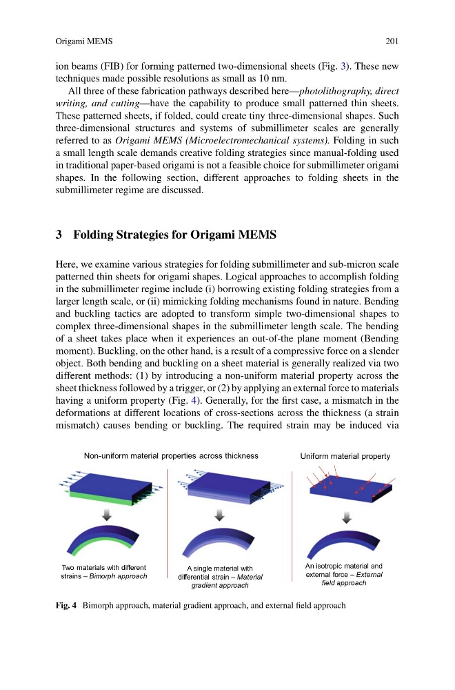
object. Both bending and buckling on a sheet material is generally realized via two
different methods: (1) by introducing a non-uniform material property across the
sheet thickness followed by a trigger, or (2) by applying an external force to materials
having a uniform property (Fig. 4). Generally, for the first case, a mismatch in the
deformations at different locations of cross-sections across the thickness (a strain
mismatch) causes bending or buckling. The required strain may be induced via
Two materials with different
strains — Bimorph approach
A single material with
differential strain — Material
gradient approach
An isotropic material and
external force — External
field approach
Non-uniform material properties across thickness
Uniform material property
Fig. 4 Bimorph approach, material gradient approach, and external field approach
201
ion beams (FIB) for forming patterned two-dimensional sheets (Fig. 3). These new
techniques made possible resolutions as small as 10 nm.
All three of these fabrication pathways described here—photolithography, direct
writing, and cutting—have the capability to produce small patterned thin sheets.
These patterned sheets, if folded, could create tiny three-dimensional shapes. Such
three-dimensional structures and systems of submillimeter scales are generally
referred to as Origami MEMS (Microelectromechanical systems). Folding in such
a small length scale demands creative folding strategies since manual-folding used
in traditional paper-based origami is not a feasible choice for submillimeter origami
shapes. In the following section, different approaches to folding sheets in the
submillimeter regime are discussed.
3 Folding Strategies for Origami MEMS
Here, we examine various strategies for folding submillimeter and sub-micron scale
patterned thin sheets for origami shapes. Logical approaches to accomplish folding
in the submillimeter regime include (i) borrowing existing folding strategies from a
larger length scale, or (ii) mimicking folding mechanisms found in nature. Bending
and buckling tactics are adopted to transform simple two-dimensional shapes to
complex three-dimensional shapes in the submillimeter length scale. The bending
of a sheet takes place when it experiences an out-of-the plane moment (Bending
moment). Buckling, on the other hand, is a result of a compressive force on a slender
object. Both bending and buckling on a sheet material is generally realized via two
different methods: (1) by introducing a non-uniform material property across the
sheet thickness followed by a trigger, or (2) by applying an external force to materials
having a uniform property (Fig. 4). Generally, for the first case, a mismatch in the
deformations at different locations of cross-sections across the thickness (a strain
mismatch) causes bending or buckling. The required strain may be induced via
Two materials with different
strains — Bimorph approach
A single material with
differential strain — Material
gradient approach
An isotropic material and
external force — External
field approach
Non-uniform material properties across thickness
Uniform material property
Fig. 4 Bimorph approach, material gradient approach, and external field approach