

Fluid Dynamics in Deformable Microchannels
157
ρ
∂u
∂t
+ u · ∇u
= −∇ p + μ∇
2 u
(18)
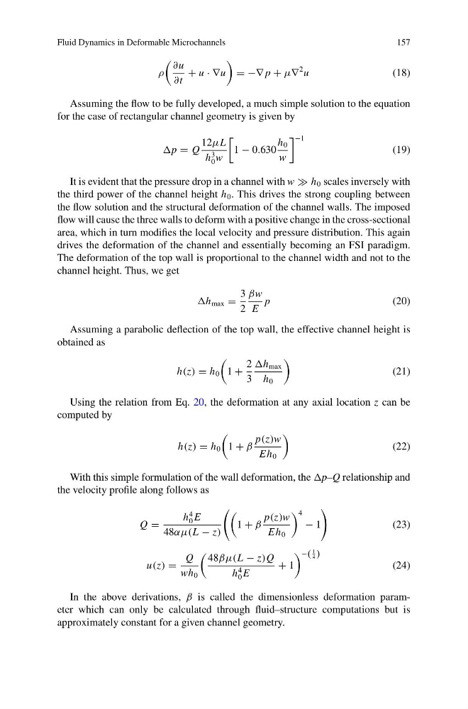
Assuming the flow to be fully developed, a much simple solution to the equation
for the case of rectangular channel geometry is given by
p = Q
12μL
h
3
0 w
1 − 0.630
h 0
w
−1
(19)
It is evident that the pressure drop in a channel with w h 0 scales inversely with
the third power of the channel height h 0 . This drives the strong coupling between
the flow solution and the structural deformation of the channel walls. The imposed
flow will cause the three walls to deform with a positive change in the cross-sectional
area, which in turn modifies the local velocity and pressure distribution. This again
drives the deformation of the channel and essentially becoming an FSI paradigm.
The deformation of the top wall is proportional to the channel width and not to the
channel height. Thus, we get
h max =
3
2
βw
E
p
(20)
Assuming a parabolic deflection of the top wall, the effective channel height is
obtained as
h(z) = h 0
1 +
2
3
h max
h 0
(21)
Using the relation from Eq. 20, the deformation at any axial location z can be
computed by
h(z) = h 0
1 + β
p(z)w
Eh 0
(22)
With this simple formulation of the wall deformation, the p–Q relationship and
the velocity profile along follows as
Q =
h
4
0 E
48αμ(L − z)
1 + β
p(z)w
Eh 0
4
− 1
(23)
u(z) =
Q
wh 0
48βμ(L − z)Q
h
4
0 E
+ 1
−(
1
4 )
(24)
In the above derivations, β is called the dimensionless deformation parameter which can only be calculated through fluid–structure computations but is
approximately constant for a given channel geometry.
157
ρ
∂u
∂t
+ u · ∇u
= −∇ p + μ∇
2 u
(18)
Assuming the flow to be fully developed, a much simple solution to the equation
for the case of rectangular channel geometry is given by
p = Q
12μL
h
3
0 w
1 − 0.630
h 0
w
−1
(19)
It is evident that the pressure drop in a channel with w h 0 scales inversely with
the third power of the channel height h 0 . This drives the strong coupling between
the flow solution and the structural deformation of the channel walls. The imposed
flow will cause the three walls to deform with a positive change in the cross-sectional
area, which in turn modifies the local velocity and pressure distribution. This again
drives the deformation of the channel and essentially becoming an FSI paradigm.
The deformation of the top wall is proportional to the channel width and not to the
channel height. Thus, we get
h max =
3
2
βw
E
p
(20)
Assuming a parabolic deflection of the top wall, the effective channel height is
obtained as
h(z) = h 0
1 +
2
3
h max
h 0
(21)
Using the relation from Eq. 20, the deformation at any axial location z can be
computed by
h(z) = h 0
1 + β
p(z)w
Eh 0
(22)
With this simple formulation of the wall deformation, the p–Q relationship and
the velocity profile along follows as
Q =
h
4
0 E
48αμ(L − z)
1 + β
p(z)w
Eh 0
4
− 1
(23)
u(z) =
Q
wh 0
48βμ(L − z)Q
h
4
0 E
+ 1
−(
1
4 )
(24)
In the above derivations, β is called the dimensionless deformation parameter which can only be calculated through fluid–structure computations but is
approximately constant for a given channel geometry.