

156
M. Kiran Raj and S. Chakraborty
as r → ∞, α r is finite.
(14)
Secondly, we require that at the wall (where the solid material interfaces with the
liquid), the normal stress in the radial direction is dictated by the fluid pressure; thus
at r = R, σ rr = −p(z)
(15)
where, importantly, the fluid pressure (p) varies along the axial (z) direction. Solving
Eq. 10 subject to the boundary conditions (14) and (15), we obtain
α r (z) =
p(z)R
2
4G
1
r
.
(16)
If the pressure gradient is assumed to be constant along z, the deformation is also
linear in z.
Finally, we arrive at the expression for the wall deformation (at r = R) along the
length of the channel with p 1 and p 2 as the inlet and the outlet pressure of the channel.
α r (z) =
p 1 +
p 2 − p 1
L
z R
4G
.
(17)
The velocity field will remain same as the parabolic profile according to the
Hagen–Poiseuille equation with the new deformed diameter D + 2α. The magnitude
of the average velocity increase along the length of the channel as the deformation
dies out.
4.2 Rectangular Channel [3]
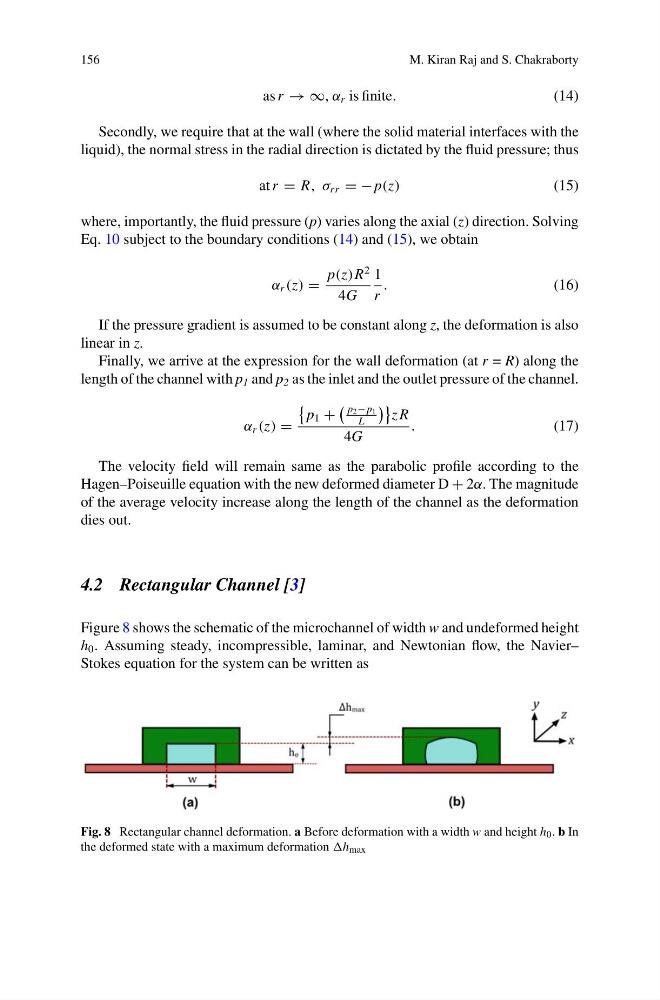
Figure 8 shows the schematic of the microchannel of width w and undeformed height
h 0 . Assuming steady, incompressible, laminar, and Newtonian flow, the Navier–
Stokes equation for the system can be written as
Fig. 8 Rectangular channel deformation. a Before deformation with a width w and height h 0 . b In
the deformed state with a maximum deformation h max
M. Kiran Raj and S. Chakraborty
as r → ∞, α r is finite.
(14)
Secondly, we require that at the wall (where the solid material interfaces with the
liquid), the normal stress in the radial direction is dictated by the fluid pressure; thus
at r = R, σ rr = −p(z)
(15)
where, importantly, the fluid pressure (p) varies along the axial (z) direction. Solving
Eq. 10 subject to the boundary conditions (14) and (15), we obtain
α r (z) =
p(z)R
2
4G
1
r
.
(16)
If the pressure gradient is assumed to be constant along z, the deformation is also
linear in z.
Finally, we arrive at the expression for the wall deformation (at r = R) along the
length of the channel with p 1 and p 2 as the inlet and the outlet pressure of the channel.
α r (z) =
p 1 +
p 2 − p 1
L
z R
4G
.
(17)
The velocity field will remain same as the parabolic profile according to the
Hagen–Poiseuille equation with the new deformed diameter D + 2α. The magnitude
of the average velocity increase along the length of the channel as the deformation
dies out.
4.2 Rectangular Channel [3]
Figure 8 shows the schematic of the microchannel of width w and undeformed height
h 0 . Assuming steady, incompressible, laminar, and Newtonian flow, the Navier–
Stokes equation for the system can be written as
Fig. 8 Rectangular channel deformation. a Before deformation with a width w and height h 0 . b In
the deformed state with a maximum deformation h max