

98
C. Ozoegwu and P. Eberhard
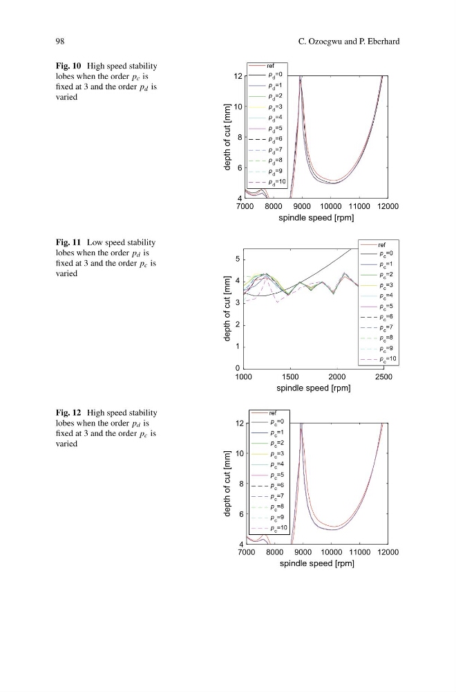
Fig. 10 High speed stability
lobes when the order p c is
fixed at 3 and the order p d is
varied
7000 8000 9000 10000 11000 12000
spindle speed [rpm]
4
6
8
10
12
depth of cut [mm]
ref
p d =0
p d =1
p d =2
p d =3
p d =4
p d =5
p d =6
p d =7
p d =8
p d =9
p d =10
Fig. 11 Low speed stability
lobes when the order p d is
fixed at 3 and the order p c is
varied
1000
1500
2000
2500
spindle speed [rpm]
0
1
2
3
4
5
depth of cut [mm]
ref
p c =0
p c =1
p c =2
p c =3
p c =4
p c =5
p c =6
p c =7
p c =8
p c =9
p c =10
Fig. 12 High speed stability
lobes when the order p d is
fixed at 3 and the order p c is
varied
7000 8000 9000 10000 11000 12000
spindle speed [rpm]
4
6
8
10
12
depth of cut [mm]
ref
p c =0
p c =1
p c =2
p c =3
p c =4
p c =5
p c =6
p c =7
p c =8
p c =9
p c =10
C. Ozoegwu and P. Eberhard
Fig. 10 High speed stability
lobes when the order p c is
fixed at 3 and the order p d is
varied
7000 8000 9000 10000 11000 12000
spindle speed [rpm]
4
6
8
10
12
depth of cut [mm]
ref
p d =0
p d =1
p d =2
p d =3
p d =4
p d =5
p d =6
p d =7
p d =8
p d =9
p d =10
Fig. 11 Low speed stability
lobes when the order p d is
fixed at 3 and the order p c is
varied
1000
1500
2000
2500
spindle speed [rpm]
0
1
2
3
4
5
depth of cut [mm]
ref
p c =0
p c =1
p c =2
p c =3
p c =4
p c =5
p c =6
p c =7
p c =8
p c =9
p c =10
Fig. 12 High speed stability
lobes when the order p d is
fixed at 3 and the order p c is
varied
7000 8000 9000 10000 11000 12000
spindle speed [rpm]
4
6
8
10
12
depth of cut [mm]
ref
p c =0
p c =1
p c =2
p c =3
p c =4
p c =5
p c =6
p c =7
p c =8
p c =9
p c =10