

80
F. Firouzi et al.
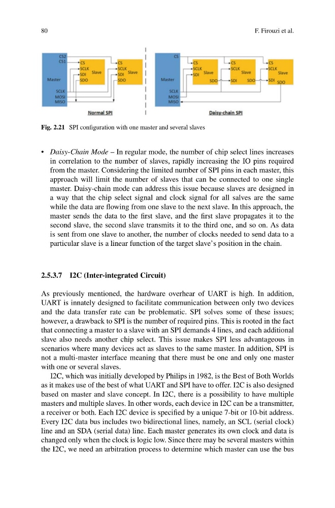
Fig. 2.21 SPI configuration with one master and several slaves
• Daisy-Chain Mode – In regular mode, the number of chip select lines increases
in correlation to the number of slaves, rapidly increasing the IO pins required
from the master. Considering the limited number of SPI pins in each master, this
approach will limit the number of slaves that can be connected to one single
master. Daisy-chain mode can address this issue because slaves are designed in
a way that the chip select signal and clock signal for all salves are the same
while the data are flowing from one slave to the next slave. In this approach, the
master sends the data to the first slave, and the first slave propagates it to the
second slave, the second slave transmits it to the third one, and so on. As data
is sent from one slave to another, the number of clocks needed to send data to a
particular slave is a linear function of the target slave’s position in the chain.
2.5.3.7 I2C (Inter-integrated Circuit)
As previously mentioned, the hardware overhear of UART is high. In addition,
UART is innately designed to facilitate communication between only two devices
and the data transfer rate can be problematic. SPI solves some of these issues;
however, a drawback to SPI is the number of required pins. This is rooted in the fact
that connecting a master to a slave with an SPI demands 4 lines, and each additional
slave also needs another chip select. This issue makes SPI less advantageous in
scenarios where many devices act as slaves to the same master. In addition, SPI is
not a multi-master interface meaning that there must be one and only one master
with one or several slaves.
I2C, which was initially developed by Philips in 1982, is the Best of Both Worlds
as it makes use of the best of what UART and SPI have to offer. I2C is also designed
based on master and slave concept. In I2C, there is a possibility to have multiple
masters and multiple slaves. In other words, each device in I2C can be a transmitter,
a receiver or both. Each I2C device is specified by a unique 7-bit or 10-bit address.
Every I2C data bus includes two bidirectional lines, namely, an SCL (serial clock)
line and an SDA (serial data) line. Each master generates its own clock and data is
changed only when the clock is logic low. Since there may be several masters within
the I2C, we need an arbitration process to determine which master can use the bus
F. Firouzi et al.
Fig. 2.21 SPI configuration with one master and several slaves
• Daisy-Chain Mode – In regular mode, the number of chip select lines increases
in correlation to the number of slaves, rapidly increasing the IO pins required
from the master. Considering the limited number of SPI pins in each master, this
approach will limit the number of slaves that can be connected to one single
master. Daisy-chain mode can address this issue because slaves are designed in
a way that the chip select signal and clock signal for all salves are the same
while the data are flowing from one slave to the next slave. In this approach, the
master sends the data to the first slave, and the first slave propagates it to the
second slave, the second slave transmits it to the third one, and so on. As data
is sent from one slave to another, the number of clocks needed to send data to a
particular slave is a linear function of the target slave’s position in the chain.
2.5.3.7 I2C (Inter-integrated Circuit)
As previously mentioned, the hardware overhear of UART is high. In addition,
UART is innately designed to facilitate communication between only two devices
and the data transfer rate can be problematic. SPI solves some of these issues;
however, a drawback to SPI is the number of required pins. This is rooted in the fact
that connecting a master to a slave with an SPI demands 4 lines, and each additional
slave also needs another chip select. This issue makes SPI less advantageous in
scenarios where many devices act as slaves to the same master. In addition, SPI is
not a multi-master interface meaning that there must be one and only one master
with one or several slaves.
I2C, which was initially developed by Philips in 1982, is the Best of Both Worlds
as it makes use of the best of what UART and SPI have to offer. I2C is also designed
based on master and slave concept. In I2C, there is a possibility to have multiple
masters and multiple slaves. In other words, each device in I2C can be a transmitter,
a receiver or both. Each I2C device is specified by a unique 7-bit or 10-bit address.
Every I2C data bus includes two bidirectional lines, namely, an SCL (serial clock)
line and an SDA (serial data) line. Each master generates its own clock and data is
changed only when the clock is logic low. Since there may be several masters within
the I2C, we need an arbitration process to determine which master can use the bus