

2 The Smart “Things” in IoT
79
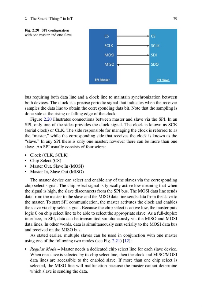
Fig. 2.20 SPI configuration
with one master and one slave
CS
SPI Master
SPI Slave
SCLK
MOSI
MISO
CS
SCLK
SDI
SDO
bus requiring both data line and a clock line to maintain synchronization between
both devices. The clock is a precise periodic signal that indicates when the receiver
samples the data line to obtain the corresponding data bit. Note that the sampling is
done side at the rising or falling edge of the clock.
Figure 2.20 illustrates connections between master and slave via the SPI. In an
SPI, only one of the sides provides the clock signal. The clock is known as SCK
(serial clock) or CLK. The side responsible for managing the clock is referred to as
the “master,” while the corresponding side that receives the clock is known as the
“slave.” In any SPI there is only one master; however there can be more than one
slave. An SPI usually consists of four wires:
• Clock (CLK, SCLK)
• Chip Select (CS)
• Master Out, Slave In (MOSI)
• Master In, Slave Out (MISO)
The master device can select and enable any of the slaves via the corresponding
chip select signal. The chip select signal is typically active low meaning that when
the signal is high, the slave disconnects from the SPI bus. The MOSI data line sends
data from the master to the slave and the MISO data line sends data from the slave to
the master. To start SPI communication, the master activates the clock and enables
the slave via chip select signal. Because the chip select is active low, the master puts
logic 0 on chip select line to be able to select the appropriate slave. As a full-duplex
interface, in SPI, data can be transmitted simultaneously via the MISO and MOSI
data lines. In other words, data is simultaneously sent serially to the MOSI data bus
and received on the MISO bus.
As stated earlier, multiple slaves can be used in conjunction with one master
using one of the following two modes (see Fig. 2.21) [12]:
• Regular Mode – Master needs a dedicated chip select line for each slave device.
When one slave is selected by its chip select line, then the clock and MISO/MOSI
data lines are accessible to the enabled slave. If more than one chip select is
selected, the MISO line will malfunction because the master cannot determine
which slave is sending the data.
79
Fig. 2.20 SPI configuration
with one master and one slave
CS
SPI Master
SPI Slave
SCLK
MOSI
MISO
CS
SCLK
SDI
SDO
bus requiring both data line and a clock line to maintain synchronization between
both devices. The clock is a precise periodic signal that indicates when the receiver
samples the data line to obtain the corresponding data bit. Note that the sampling is
done side at the rising or falling edge of the clock.
Figure 2.20 illustrates connections between master and slave via the SPI. In an
SPI, only one of the sides provides the clock signal. The clock is known as SCK
(serial clock) or CLK. The side responsible for managing the clock is referred to as
the “master,” while the corresponding side that receives the clock is known as the
“slave.” In any SPI there is only one master; however there can be more than one
slave. An SPI usually consists of four wires:
• Clock (CLK, SCLK)
• Chip Select (CS)
• Master Out, Slave In (MOSI)
• Master In, Slave Out (MISO)
The master device can select and enable any of the slaves via the corresponding
chip select signal. The chip select signal is typically active low meaning that when
the signal is high, the slave disconnects from the SPI bus. The MOSI data line sends
data from the master to the slave and the MISO data line sends data from the slave to
the master. To start SPI communication, the master activates the clock and enables
the slave via chip select signal. Because the chip select is active low, the master puts
logic 0 on chip select line to be able to select the appropriate slave. As a full-duplex
interface, in SPI, data can be transmitted simultaneously via the MISO and MOSI
data lines. In other words, data is simultaneously sent serially to the MOSI data bus
and received on the MISO bus.
As stated earlier, multiple slaves can be used in conjunction with one master
using one of the following two modes (see Fig. 2.21) [12]:
• Regular Mode – Master needs a dedicated chip select line for each slave device.
When one slave is selected by its chip select line, then the clock and MISO/MOSI
data lines are accessible to the enabled slave. If more than one chip select is
selected, the MISO line will malfunction because the master cannot determine
which slave is sending the data.