

9 Emerging Hardware Technologies for IoT Data Processing
459
otherwise, the output is 0. This functionality matches the definition of the majority
vote, which is leveraged to implement the vertical computation step in the bit-serial
median filtering algorithm.
Performing In Situ Bit Comparison Figure 9.22(b) shows an illustrative example
circuit for performing in situ bit comparison using two serially connected memristive elements. Depending upon the input voltage (V) and the states of memristive
elements (r 0 and r 1 ), the output voltage (v out ) varies between V and 0. According to
parts (c) and (d) of Fig. 9.22, v out represents the results of a binary XOR/XNOR on
v and r. This novel functionality is used in the bit-serial median filter for finding the
minority bits, as well as in the k-medians algorithm for searching and selecting all
the members of a dynamically formed cluster prior to finding new centroids.
9.5.5 MISC Building Blocks
The MISC accelerator is designed based on three fundamental building blocks: a
memory cell, a majority unit, and a network reduction unit. The building blocks are
designed and optimized to achieve high memory density, low-energy consumption,
and capacity for massive parallel computation at the memory cells.
9.5.5.1 Memory Cell
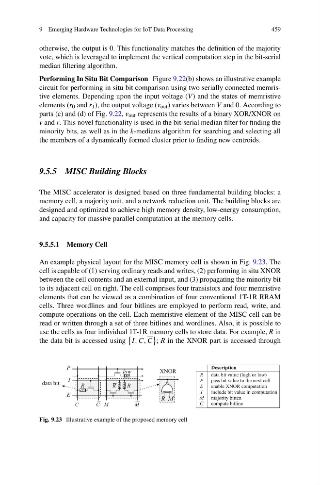
An example physical layout for the MISC memory cell is shown in Fig. 9.23. The
cell is capable of (1) serving ordinary reads and writes, (2) performing in situ XNOR
between the cell contents and an external input, and (3) propagating the minority bit
to its adjacent cell on right. The cell comprises four transistors and four memristive
elements that can be viewed as a combination of four conventional 1T-1R RRAM
cells. Three wordlines and four bitlines are employed to perform read, write, and
compute operations on the cell. Each memristive element of the MISC cell can be
read or written through a set of three bitlines and wordlines. Also, it is possible to
use the cells as four individual 1T-1R memory cells to store data. For example, R in
the data bit is accessed using
I, C, C
; R in the XNOR part is accessed through
R M
XNOR
R
R
R
low
M
M
C
P
I
E
C
data bit
R
P
E
I
M
C
data bit value (high or low)
pass bit value to the next cell
enable XNOR computation
include bit value in computation
majority bitten
compute bitline
Description
Fig. 9.23 Illustrative example of the proposed memory cell
459
otherwise, the output is 0. This functionality matches the definition of the majority
vote, which is leveraged to implement the vertical computation step in the bit-serial
median filtering algorithm.
Performing In Situ Bit Comparison Figure 9.22(b) shows an illustrative example
circuit for performing in situ bit comparison using two serially connected memristive elements. Depending upon the input voltage (V) and the states of memristive
elements (r 0 and r 1 ), the output voltage (v out ) varies between V and 0. According to
parts (c) and (d) of Fig. 9.22, v out represents the results of a binary XOR/XNOR on
v and r. This novel functionality is used in the bit-serial median filter for finding the
minority bits, as well as in the k-medians algorithm for searching and selecting all
the members of a dynamically formed cluster prior to finding new centroids.
9.5.5 MISC Building Blocks
The MISC accelerator is designed based on three fundamental building blocks: a
memory cell, a majority unit, and a network reduction unit. The building blocks are
designed and optimized to achieve high memory density, low-energy consumption,
and capacity for massive parallel computation at the memory cells.
9.5.5.1 Memory Cell
An example physical layout for the MISC memory cell is shown in Fig. 9.23. The
cell is capable of (1) serving ordinary reads and writes, (2) performing in situ XNOR
between the cell contents and an external input, and (3) propagating the minority bit
to its adjacent cell on right. The cell comprises four transistors and four memristive
elements that can be viewed as a combination of four conventional 1T-1R RRAM
cells. Three wordlines and four bitlines are employed to perform read, write, and
compute operations on the cell. Each memristive element of the MISC cell can be
read or written through a set of three bitlines and wordlines. Also, it is possible to
use the cells as four individual 1T-1R memory cells to store data. For example, R in
the data bit is accessed using
I, C, C
; R in the XNOR part is accessed through
R M
XNOR
R
R
R
low
M
M
C
P
I
E
C
data bit
R
P
E
I
M
C
data bit value (high or low)
pass bit value to the next cell
enable XNOR computation
include bit value in computation
majority bitten
compute bitline
Description
Fig. 9.23 Illustrative example of the proposed memory cell